If you are looking for pictures of temporary electrical installations, they can be found at another post,
Temporary electrical installation pictures and
Temporary lighting installation pictures.What you will find below are mostly on permanent installations.
Picture 1 – Conduit and trunking

The above picture shows how the electrical conduit and trunking installation should be coordinated with water pipes.
Trade subcontractors (water piping sub-contractors, electrical sub-contractors, telephone cabling contractor, computer network contractor, etc) must not be allowed to proceed with the installation of their individual services and equipment on the “first come, first served basis”.
=== RELATED POSTS:
Pictures of electrical wiring |
===================
Prior to the commencement of the installation works by trade sub-contractors, a set of proper coordinated drawings, endorsed by all relevant parties, should be made available to all the sub-contractors involved in a particular area.
Feedbacks from them should be heard because they are the ones who will be doing the works. Many times, what are nicely shown on approved drawings cannot be practically constructed at site.
You will find more pictures on this matter in
Electrical conduit and trunking pictures.
Picture 2 –
Electrical grounding electrode and chamber

An electric shock protection system depends on heavily on the availability of good and reliable connection to the earth mass.
Without the low resistance to earth, the users of electricity face a very high risk of electrical injuries and electrocution.
Therefore, the connection to the grounding electrodes must be properly installed, protected from accidental damage and easily available for inspection and maintenance.
The component used to house the earthing connection to the grounding rod is called earthing chamber.
Picture 2 above shows an example of such a chamber. It is usually made of concrete materials and provided with removable cover.
Inside the chamber, what you see is the earthing copper tape that has been connected to the earthing electrode. However, in this picture the connection is not so visible.
Picture 3 below gives you a better view of a connection to the earthing rod. This earthing point was still under construction when the picture was taken. So the earthing chamber was not put into place yet.
Because of that, you can have a good view of the connection between the earthing conductor and the grounding electrode.
Picture 3 –
Connection between an earthing conductor and the grounding rod

See more of the earthing chambers and the electrode connections in this post,
Electrical grounding electrode pictures.
Picture 4 -
Down light pictures

Down light are one of the most popular types of lighting fixtures inside buildings.
It is not a new type of light fittings. but with the popularity of compact fluorescent lamps, the surge in the use of downlights has increase dramatically.
I will be talking about these types of light fittings soon, but i have already sent a few pictures of down lights and other types of fluorescent light fixtures at this post,
Recessed down lights installation.
Diagram 5 –
Sectional diagram of a simple lightning protection system

I have sent a post on
Lightning earth rods installation. It is the first of a few posts on the subject of lightning protection system for buildings.
There are a few pictures there, but I have not yet uploaded really good pictures on lightning protection.
However, the content of the article is suitable for beginners who wish to get some overall knowledge on the issues of lightning strikes and lightning protection.
Check it out.
Picture 6 -
Installation of lightning air termination network

This is part of a lightning air termination network. The installation work at the roof of this building is actually in progress now and is not yet completed.
However, I have taken a few pictures of what has already been installed. You can see the rest of the pictures at this post,
Lightning roof conductor installation.
Picture 7 -
Leaking hose reel pipe

Why do I show you a picture of leaking hose reel water pipe?
Because water and electricity do not mix, yet there are many water piping of all types running around inside a building near our electrical cables, equipment and appliances.
Many of serious electrical accidents and injuries have been a direct result od water that come into contact with electricity.
Even when no accident occurs, electrical equipment would get damaged when it is involved with water unless is has been designed to be so.
Visit this post,
Electrical panel under water pipes, to read a few pictures of one case that I recently documented.
Picture 8 –
Typical busduct rising main at individual building floors

The above picture shows a typical installation of busduct rising mains in the riser room at individual floor of a high rise building.
This picture was taken in the riser room at one of the upper floors of a high rise building.
From the picture you can see most of the major components of a busduct riser system.
(NOTE: for readers who are not from electrical disciplines, a “riser” is a feeding cable or pipe giving supply to upper floors of a multi-storey building.
In electrical works, a riser is a set of cables the supply the upper floors. The electrical distribution diagram in Diagram 3 may make you understand this better.
The feeding cables “rise” up straight to the top floor. Then at each floor a tap-off unit is connected so electricity can be supplied to that floor.
An alternative is to run one individual set of cables to each floor. Then there would be many cables that need to be installed the number of which is directly proportional to the number of upper floors.
One single set of bigger cables is always cheaper to install and much easier to handle.)
Observe that there are three tap off units there: two units of 60A three phase, and one unit of 100A three phase. The one at the highest position of the three is the 100A tap off.
Why three units?
Visit this post,
Electrical busduct installation pictures, to read more and see more pictures and diagrams of busduct risers in multi-storey buildings.
Picture 9 -
Surface conduit installation
 Why do we need these conduits?
The conduits are used to protect the wiring cables that carry the electrical current.
Electricity is dangerous. Even though the electric conductors that carry the current is insulated by some PVC covering materials or whatever, the covering material is not strong enough to protect the cable from damage.
When the covering is damaged, the electrical conductor inside may be exposed to touch or it can also unintentionally come into contact with things that can carry electric current.
This scenario would present a high risk of electric shocks.
Therefore, we protect the electric cables so that they do not present the dangers of electric shocks to people (or animals).
A second reason to protect the cables is to make sure the electrical system stays reliable.
When the cable PVC covering is damaged, the conducting metal can come into contact with other metals that are in contact with earth.
Visit this post,
Electric conduit installation pictures, to see a few more conduit pictures.
Picture 10 –
HV substation’s main earth bar

What you see in the above picture is the HV substation’s main earth bar. The purpose of having the main bar is simple.
All earthing conductors inside the HV room would be connected to this bar. That is the reason you can see in Picture 2 a number of ready-made termination holes complete with bolts, nuts and spring washers.
Notice the main copper earthing tape mounted along the substation wall in Picture 1. This is the main equipotential earthing conductor for this electrical room.
It should run through all perimeter walls of the room at a height of approximately 12 inch from the substation’s finish floor level. That is why you can see that in Picture 2 the left-most and right-most terminals have been connected with a horizontal copper tape conductor.
An ideal installation would have the main equipotential conductor run in a ring around the perimeter walls and both conductor ends connects to the main earth bar at the left-most and right-most terminals.
There are more pictures of the main earth bar at this post,
Substation main earth bar pictures.
Picture 11 –
Dangerous electric panel installation

Why would I want to show you these pictures?
There was something wrong with this electric panel installation. The telephone DP on the right is not a problem, but the installation of the electrical panels was absolutely not acceptable.
This project was a high-rise office building.
At every floor there were a number of electrical panels to serve all the lighting and power loads on that floor including the lighting, switched socket outlets, toilet exhaust fans etc, etc.
A few of the panels were located inside the riser room of each floor.
However, since each was a large area some panels needed to be located at the office area. Wiring directly from the electrical riser would be unnecessarily too long and a waste of wiring cost.
Therefore, the electrical consultant proposed that these electrical panels be located along the corridors throughout the building. The design architect was requested to provide small rooms to house the panels.
Alternatively, small electrical cabinets with lockable doors and sufficient work access and ventilation would be acceptable.
Read the full article at this post,
Electric panel installation pictures. There are some more pictures there too.
Picture 12 –
Electric trunking running below soffit of a concrete floor slab

No electrical installation work of a significant size can be done properly without the use of an electric trunking.
A trunking is a larger size of a conduit. When you need to run a number of electric conduits along each other for a significant distance, then consider using a trunking in place of the conduits. There are so many sizes you can choose from.
The above picture is an example of a trunking installation above ceiling level, under the soffit of the concrete floor slab.
I also labeled some of the other services there for the benefit of those non-electrical readers who need pictures like this for reference, to know what is what among the myriads of pipes, conduits and trunking running above the ceiling level.
Visit
Electric trunking installation pictures to see more pictures on electrical trunking and how they are installed.
Picture 13 –
Cast in situ light pole mounting base

Some readers may say that this is a strange way to locate a light pole, which is above the drain. A more normal method would be more or less like the one in Picture 13 below.
Picture 14 –
Precast concrete base for compound light poles

Here the design-and-build contractor had a problem of locating a few of the compound light poles at an open carpark area because there were several drains running between carpark boxes.
These drains were supposed to be located at the boundary of the land being developed.
However, it turned out that with the presence of the drains the actual land space for the landscaping works (e.g. trees, shrubs, etc) was too narrow to grow larger trees.
Therefore, the client agreed that the drains be relocated through the middle of the carpark area.
Construction people tend think that electrical things are very flexible and easy to be moved and kicked around just like a wiring cable.
I never liked that notion. It is true in this case, however.
The main contractor asked me how to place the pole bases on top of the drain cover.
I told them that the only real solution I have ever seen in such situations was only by constructing a cast in concrete base together with the drain, with the construction drawings of the light pole’s concrete foundation designed and endorsed by the civil work’s design consultant.
The result was what you see in Picture 12 above. More of these pictures can be seen at this post,
Compound Lighting Installation Pictures.
Picture 15 –
MATV antenna brackets mounted to a roof wall

When I started this blog, I wanted to make it specialized in only electric supply systems for building constructions and its related construction works.
However, I have also always asked myself what to do with all the pictures on ELV (extra low voltage) systems and telephone works that I took during my works.
In fact I have quite a number of pictures on the installation of other building services such as the public address system, the firemen intercom, audio visual and conference system, etc.
It has been such a waste. Those pictures can be of use to many people such as those whose need real installation pictures of the systems in real construction works.
Even I myself was having such needs during my early days in the electrical world. Of course, now anyone can search among the tens of thousands of the manufactures’ and suppliers’ websites specialized in these systems.
However, often we only find nice pictures and often we do not want nice pictures.
We want the real construction pictures, pictures that are not biased towards any particular supplier or manufacturer.
For this reason, I am expanding the scope of this blog to also include the installation pictures of building’s extra low voltage (ELV) services and telecommunication systems.
Today interested readers can see a few pictures on the installation of MATV antenna brackets. An MATV single line schematic diagram is also shown. Visit this post,
MATV Antenna bracket pictures.
Picture 16 –
How to install a motorized overhead projector

I took this picture a few months back.
The electrical contractor produced a mock-up unit of the installation bracket for motorized overhead projector.
I just sent it here plus a few more for anybody who has no idea at all how it is done.
The overhead projector was for meeting rooms. There were about thirty units to be installed through the building.
This one was done so I could check and comment.
You can see all the pictures at this post,
How to install overhead projector.
Picture 17 -
Compound lighting feeder pillar

A building construction of significant size is usually not complete without at least one small outdoor weatherproof feeder pillar.
I have uploaded a few pictures of feeder pillar including existing and new ones at this post,
Feeder pillar single line diagram.
There are also a few diagrams there including the cubicle dimensions of a feeder pillar and a simple single line diagram.
Picture 18 –
Fire-rated (FR) cables installed on vertical cable tray

The above picture shows the installation of FR electrical cables.
There is nothing special about the installation of the fire-rated (FR) cables. Even though these cables are a direct replacement of mineral insulated copper cables (MICC) for high-rise buildings, the installation here is the same as for normal XLPE or PVC-insulated cables.
In Picture xx, two vertical submain circuits employ FR cables installed on a vertical cable tray. These cables were taken in a cable riser room at a multi-storey building.
All these cables are single-cores. The circuit on the right (with the smaller cables) was supplying the lift motor room at the roof level of the building.
The copper tape on the right edge of the vertical cable tray is the common earth and it is connected to the main electric grounding bar at the LV Room on the ground floor of the building.
The LV Room houses all main switchboards (MSB’s) for the building’s low voltage electrical distribution.
The circuit on the left edge of the cable tray was supplying two fan rooms, which were also at the roof level.
The loads of the fan rooms were mostly electric driven motors that run fire protection fans. These include smoke spill fans, staircase pressurization fans, etc.
These fan loads are significantly large. That is why the cables are of bigger size than those for the lift motor room electrical panel.
You can see more of the pictures at this post,
FR electric cable installation pictures.
Picture 19 –
1000 KVA standby diesel generator

No building of a significant size can be operated without at least a small standby generator installed.
The primary reason for having the standby generator is for fulfilling the requirements of the fire department to have the supply readily available for operating the fire protection and fire fighting equipment.
The building itself would normally have some equipment and lighting that need to be operable even when the public electricity supply fails.
This would require the use of a back-up generator or a supply battery system.
See more installation pictures of the standby diesel generator at this post,
Standby electric generator pictures.
This is the first part. I still have more pictures of this installation which will be uploaded soon. Keep checking this post for updates.
Picture 20 –
Bollard light

Well, I thought this bollard light looked nice at the children playground near at rest area and food stalls on my way from my workout routine at a local gym.
I do not have much to say about the bollard lighting. They are just pictures of existing lights that I thought may be useful to someone.
However, for readers who have to deal with the installation of this type of landscape lighting, I did attach in this post a section diagram that shows a little bit more details. I hope it helps.
Landscape lighting falls within the jurisdiction of landscape architects. So I do not normally spend much time with them.
When I have to prepare an external lighting layout that also include the landscape lighting during a concept design stage, I usually just copied the layout of landscape lighting from previous projects, prepare the electrical distribution system for the lights and count the number of light fixtures.
The purpose was to capture a rough approximate of the cost for the landscape lighting works. We must get the money first. Once the money is available, there are so many ways to get the job done.
See more of the bollard light pictures at this post,
Bollard light pictures.
Picture 21 –
Electric closet

The electric closet in the above picture has been done for a multi storey office building.
I wrote an article earlier on the protection of electrical panel at a multi storey office building. You can read the article here,
Electric panel installation pictures.
In that article I gave a storey of how reluctant the main contractor was to provide an electrical room or cabinet in order to restrict access to the electrical panels and protect them from damages.
Access to the panel by unqualified people may lead to abuse, improper operation of the instruments inside the panels, or accidents by touching the LIVE parts inside the panels.
These panels were three-phase panels with 415V of voltage between the phases. Accidentally touching the live parts at this voltage would lead to very serious injuries. Electrocutions and immediate deaths are common results of electric shocks at this voltage.
Read the rest of the article here,
Multi storey building electric closets.
Picture 22 –
Substation CO2 fire protection cylinders being installed

All electrical substations and main switchrooms need to be provided with a fire protection system.
If the substation building is a separate building, some local offices of the electricity supply authority and the local office of the Fire Department may consider portable fire extinguishers as adequate.
However, electrical rooms that are part of an occupied building are usually required to have some form of automatic fire extinguishing system such as a CO2 system.
The above picture shows a CO2 automatic fire extinguishing system installed inside a standby generator room.
Picture 23 below show an automated fire curtain right above the inside opening of the genset room’s air intake silencer.
The curtain sheet is in the rolled-up state. When the automatic CO2 system is activated and the gas discharged, this curtain (and all other fire curtains installed in the room) is automatically released and rolled down to block the air passage.
This action allows the CO2 gas to totally flood the room and extinguish the fire inside.
Picture 23 –
Automatic fire curtain over fresh air inlet silencer

What fire protection to be used for an electrical substation depends on the preference of design consultants and the minimum requirements of the local Fire Authorities.
However, in some projects, a substation building or substation room (e.g. HV switchgear room) needs to be constructed and equipped (excluding the electrical distribution system equipment), and then handed over to the local electric supply authority as one of the agreed conditions to obtain the supply.
In these types of arrangement, the minimum requirements and preferences of the local office of the electric supply authority must also be met.
The fire authorities usually have an established requirement of what system is required in a substation room. The design engineers usually prepare their design based on these requirements and the supply authority’s requirements.
See the rest of the pictures here,
Substation fire protection system.
Pictures of electric shock injuries
I have uploaded a few pictures of electric shock injuries, but I know many readers are easily turned off by the sight of these serious injuries. So I do not put them in this post.
You can check out this post to see them,
Electric shock injury pictures.
Diagram 24 –
Electrical riser room

During the design of an electrical installation for a building, spaces that are required as electrical rooms need to be provided for very early in the planning and design process.
I will try to present this in a form of a few basic concepts so that non-electrical readers can benefit from it.
There are also a few diagrams at the end of this post, but I do want to go too technical here as this may turn off the non-electrical readers.
If you need a more technical discussion, I will send a few posts of electrical substation layout and design in future.
Read this article here,
Building's electrical rooms layout.
Picture 25 –
Dangerous feeder pillars
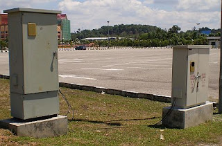
I think anybody with even a minimal amount of knowledge on the hazards presented by electrical equipment installed in public places know what is wrong with the feeder pillars in the picture above.
I am not talking about age of the feeder pillars.
I know that everything gets old some day. Machines get worn out, the materials get deteriorated and the lovely paintwork fades out.
They do get old, just like us.
However, machines and equipment that can endanger people especially children should be designed and installed with safety as the most important criteria.
The feeder pillars above have failed in that respect.
Read this article here,
Feeder pillar hazard pictures.
Picture 26 –
The inside view of the electrical socket extension unit
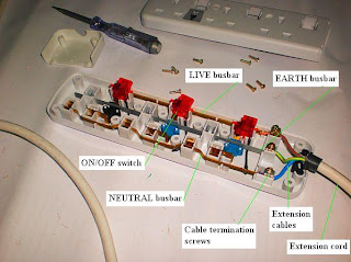
Have you ever wondered how it looks inside the extension unit of an electrical power socket? The pictures in this post can help you appreciate what is going on inside this piece of common household items.
I think most readers can understand the picture clearly with the labels that I added.
However, for the benefits of absolute beginners that need explanations on what does what in this picture, let me just give brief descriptions.
Visit the post here,
Electrical socket extension unit.
Diagram 27 –
Simple house electrical layout

Anybody looking for a layout and schematic diagram of a simple electrical installation?
The above electrical layout is very old.
At least 30 years old or more.
You can see that by the number of electric socket outlet in the bedrooms and the kitchen.
A modern bedroom would need at least a few sockets in each room. You would need one for the table clock, table lamp, a television maybe, etc etc.
One electrical socket as shown in the electrical layout would definitely be not enough.
However, I believe there are still great many areas in this world that still lacks even the basic supply of household electricity.
So this simple house electrical design is still useful to great many people.
In fact, this design is more relevant. It is also more easily understood by beginners of electrical installations.
Read this post,
A simple electrical installation, for a full article and the single line diagram for the above layout.
Picture 28 –
Underfloor trunking installation work in progress

The underfloor trunking system has been around for a long time. The first time I saw it was inside an application guide published by a public telecommunication company.
The technical manual was already very old and I was in the first year of real professional work after my graduation. That was 23 years ago.
Why do we need an underfloor trunking system?
An underfloor trunking system is an alternative way of providing the dedicated routes to run electrical cables, telephone cables or any other wiring cables you can think of.
I said “wiring cables”. An 11KV cable is not a wiring cable. A 25 sq.mm electrical feeder cable to supply an 11 KW fire pump panel is not a wiring cable.
(Note: 25 sq.mm means 25 millimeter square. It is a measure of the net cross-sectional area of the electrical conductors of an electric cable).
The 1.5 sq.mm cables that are used for wiring the office lights are categorized wiring cables.
See the underfloor trunking pictures here:
Underfloor trunking pictures.
Picture 29 – Sharp edges of a site-fabricated 45-degree electrical trunking bend

What will be the problem if an electrical contractor fabricates some of the accessories of an electrical trunking system by hand at the construction site? Why do I make an issue of this matter?
Majority of Clients and Consultants that I know specifically state that all electrical trunking and the related accessories should be factory-manufactured and should preferably be obtained from the same manufacturer.
This means that all parts and pieces that make up an electrical trunking installation should be purchased as finished products from factory.
What if the electrical subcontractor does not follow this requirement?
Factory-manufactured accessories have much better quality; there is no doubt about that.
However, is there any other significant reason for this specific requirement other than the difference in qualities of the products?
Read the full article at this post,
Site-fabricated electrical trunking. There are a few more pictures there too.
Image 30 –
Dimensions of a concrete foundation for a 5m compound light pole

A friend asked for the size of this thing. So I uploaded a few images.
Read the full article at this post,
Compound lighting foundation size. There are a few more images there too.
Picture 31 –
The electrical manhole being unloaded

The picture above shows an electrical manhole intended for underground installation being unloaded from the transport truck.
Most building works require at least one or two underground electrical manholes. That is because a building of significant size usually require a few hundred amperes of electric current at low voltage (i.e. 240 volt, 3 phase current).
Above a few hundred KVA (kilo-volt-amperes), the electricity supply authority usually delivers the electrical power to the consumer loads at higher than 240 volt, usually at 11,000 volts.
(Note: 100 amperes x 240 volt x 3 phases = 24,000 VA x 3 phases = 72,000 VA = 72 KVA. For readers who are intimidated by the KVA term, this is what KVA is. That is measure of electrical power delivered to a building. It is also the most common unit used in specifying the size and rating of electrical equipment and switchgears.)
Okay, back to the electrical manhole.
When the supply is at 11,000 volts (i.e. 11 KV), high voltage cables installed below ground level (i.e. underground) is the most popular method of electricity distribution unless the building is in remote areas such as the countryside.
So, in building works, we need at least one or two of these manholes to bring in the authority cables from outside the boundary of the building works to the electrical substation inside the building compound or the inside the building itself.
Read the full article at this post,
Underground electrical manhole.
Picture 32 –
Improvised installation of electrical trunking, air-conditioning ducts, fire protection pipe work and a floor beam

The few pictures that I show in this post are a demonstration of what can happen when a proper coordination is not carried out between the mechanical and electrical services installation in a multi-storey building.
Somewhere among my previous posts, you can find examples of good coordination between the mechanical and electrical services installation.
However, here I wish to show you the opposite side of it. The above is not the worst case examples. I have plenty of pictures showing much worse scenarios which I will show you in future posts.
A reminder for the beginners in electrical installation works: Learn from the mistakes that other people have done and plan your work accordingly.
This is a very expensive lesson if you have to learn it from personal experience because rectifications, relocation or corrections in large installations can be very expensive and time consuming.
Read the full article at this post,
M & E Coordination.
Picture 33 –
Example color codes for a few electrical services

This post gives some examples on the identification of the different electrical services inside a building.
The three conduits with the color code bands in the above pictures are part of what we call in building works as electrical services.
However, electrical services are not the only ones that require some means of identifying what they are for.
Mechanical services also really need their piping, trunking, etc to be provided with some identification.
In some installations such as hospitals, there are so many services under the mechanical category. At certain locations in a hospital complex, it is almost impossible to know which pipe is for what. (Remember that an electrical G.I. (galvanized iron) conduit is just a metal pipe.)
During maintenance, long after we the construction people have completed and commission the building with all the mechanical and electrical services fully tested and operational, the maintenance people could be cursing us every week for not providing sufficient identification for each of the services inside the building.
During operation and maintenance of the building, insufficient identification on each of the services throughout the building can lead to serious accidents.
Why do I talk about mechanical services? Because they often run along the electrical services. Now and then the parts and materials between the two disciplines look and feel just the same.
Read the full article at this post,
Electrical Services color codes.
Picture 34 - 1600 kVA transformer delivery pictures

I just uploaded some pictures of 1600KVA transformers being unloaded from the delivery truck at a project site.
You can see all the pictures here,
1600 kVA Transformer Pictures
Picture 35 –
10 meter light poles: the lower piece
I took a few pictures of the storage area for compound lighting parts at a project site recently. With these pictures I think I have explained the whole system of compound lighting in this blog. So this post wraps up the topic of compound lighting. Of course, if I find more pictures that I think readers would be interested in, I will attach a link to this post also.
See all the pictures at the storage yard here,
Compound lighting storage yard.
Picture 36 –
The mould for exothermic welding for jointing 25mm x 3mm grounding copper tape and a copper-jacketed steel ground rod.
I believe I have uploaded to this blog quite a number of pictures on electrical grounding. However, there is one work of the grounding system that I have always wanted to show the readers especially true beginners (i.e. students and young engineers). That is the process of exothermic welding.
The above picture is one of the few that I just uploaded. You can see the rest of them here,
Electrical grounding .
Picture 37 –
Cable ladders at Consumer’s High Voltage Switchgears
Cable ladder is one of the most important components of a building’s cable support system. The above picture show an example of a new installation. You can see the rest of the pictures at this post,
Cable ladder pictures.
Picture 38 –
Electrical and mechanical services above the ceiling of an office building
Some few weeks ago a reader left a message on one of my blogs asking how to connect a branch conduit to a steel trunking. So I uploaded to this post a few pictures showing the connections between electrical conduits and trunking. Those pictures should be self-explanatory enough how to make the connection. See all the pictures here,
Conduit to trunking connections.
Diagram 39 –
Overall layout of the substation electrical rooms for a new office building
Below is the layout of the electrical rooms for a post that I sent earlier, Cable ladder pictures.
The earlier post was about cable ladders. I know it can be difficult for some beginners to imagine the overall arrangement of the electrical rooms (and therefore the cable ladders) at the substation without the aid of some layout diagram.
The above diagram should be able to give some help.
You can read the rest of the post here,
Substation rooms layout diagram.
Picture 40 -
Exothermic welding process set-up labeled
The above picture shows the set up for a cable to cable
connection.
I will not write much today and I have serious doubt that I
will be able to write long posts again in the near future.
The best I can do is to show you some pictures. When I have
more time I will write longer.
Note that the part that I labeled “explosive powder” is not
really explosive powder. Well, IT IS explosive, but it is not an EXPLOSIVE.
It is actually some powdered mixture of copper oxide and
aluminium.
When ignited, the mixture produces a very high temperature reaction
that molten the copper and aluminium components which then flow into whatever
cavities between the conductors to be joined, as well as form a thick layer of
alloy envelope around them.
Picture 41:
Underfloor trunking below structural rebars
I have published quite a number of pictures on underfloor trunking systems.
These underfloor trunking systems, together with their floor draw boxes (i.e. junction boxes) and floor service boxes, have so far been installed inside the concrete screeding of the concrete floor.
In this installation method, the reinforced concrete floor slab is constructed first.
However, the construction of the concrete floor is not yet completed with the completion of the reinforced concrete.
A layer of concrete 50mm to 75mm thick is to be poured and leveled on the finished reinforced concrete to make a finished concrete floor. This layer is called 'concrete screeding'.
It is within this top concrete layer that an underfloor trunking system is installed, or "embedded" as some people call it.
However, in the new picture that I showed above, the underfloor trunking is not installed in the screeding layer (In fact there is no screeding layer here).
The finished floor level here has been designed to be just 50mm above the top of the top of topmost reinforcement steel bars (called "rebar").
Read the rest of the article here:
Underfloor trunking below structural rebars
Picture 42 -
Electric cable bridge
(Click on the picture to enlarge it)
Continuing the tradition of sharing engineering knowledge through pictures, today I am sharing with you some pictures of cable bridges for electrical cables.
Visit
Electric cable bridge to see more photos of cable bridges for electrical cables.
Picture 43 -
Electric cable drums

It is very important that great care is exercised at all times when handling cables.
Every precaution should be taken to avoid dropping a drum of cable. Dropping off cable drums, even from a short height, will flatten the layers of the cable nearest to the barrel of the drum.
Depending on the length of the cable, the type of the cable involved and the height of the drop, the weight from the outer layers can cause damages to the inner layers that are very difficult to ascertain.
Similar distortion to the cable will also occur if the drum falls on its sides.
I have a true story to tell on mis-handling of cable drums. It was from one of my earlier projects. Read it here,
Electric Cable Drum Pictures.
Picture 44 -
A weather-proof 13A IP66 power socket
This picture is from one of my old projects.
The location is on the roof top of an attached 5-storey podium block. This level is used as a secondary plant room where air-condition cooling tower and fire fighting water tanks are located.
A fire fighting main pump room is also nearby here.
Therefore, this outdoor area is a good location as a maintenance work area that may be required once the office complex is operational.
The conduit that you see along the parapet wall runs all around the roof top. IP66-rated outdoor power sockets and bulk-head lighting fixtures are installed at uniform intervals along the conduit run.
See the post and more weather-proof socket outlets here,
Weatherproof 13A switched outlets
Copyright http://electricalinstallationwiringpicture.blogspot.com Electrical installation pictures


.jpg)


