Picture 1 – Earthing chambers

=== RELATED ARTICLES: Exothermic welding: Cable to cable connections | Electrical grounding | Substation main earth bar pictures | Switchboard earthing pictures | Lightning roof conductor installation | Lightning Earth Rods Installation | Temporary Electrical Earthing Pictures | A simple electrical installation | Electrical socket extension unit | 1- Phase ELCB connection pictures | Bare fluorescent light pictures | Recessed down lights installation | Bollard light pictures | Light switch installation pictures | Home wiring pictures | Electric Meters | Most Basic Principles of House Wiring | MATV antenna bracket pictures | Electrical installation pictures | Temporary electrical installation pictures | Temporary lighting installation pictures
=================
Grounding electrodes are driven several feet into the ground soil using a hammer or powered rod driver tools.
The connection is made at the top of each electrode to the earthing conductor coming from the electrical equipment to be grounded, or the down conductor of the lightning protection system.
This connection must be protected and it should be available for inspection and servicing in the future. It is therefore enclosed inside a chamber that is provided with a removable cover so that the grounding connection is easily accessible.
Picture 1 above is an example of the earthing chambers. This one is one of the smaller-sized types, approximately 8 inch by 8 inch of internal clearance inside the square chamber. Some designs are bigger.
Picture 2 below shows the same grounding chamber with the cover removed. Notice the strong metal pull eye provided to help removal of the cover. The earth chamber is installed in the ground and over time the gaps between the cover and the chamber are eventually filled with dirt, sand and soils. This makes the opening of the cover very difficult sometimes.
Picture 2 – The earthing chamber with the cover removed

What you can see inside the chamber in Picture 2 is the earthing copper tape that has been bonded to the grounding electrode. Picture 3 shows the bonding this better.
Picture 3 – Another view of the grounding chamber

Picture 4 – Closer view of the grounding rod

I have attached a diagram (see Diagram 5 below) that gives an overall picture of the installation of the electrical grounding electrode.
Diagram 5 – Grounding electrode and earth chamber

From the diagram you can see how the earthing copper tape is installed below ground and enter the grounding chamber from below. Then the end of the copper tape is connected to the top of the electrode using a clamp.
However the copper tape connection to the earth rod in the above pictures does not use a clamp. That is why you cannot see any sign of a clamp in the picture.
The earthing connection in this case uses thermo-weld bonding. That is the reason you can see the copper see to connect to the vertical rod at ninety-degree angle. The thermo-weld joint can be done much easier in this formation.
Whether the choice is to use the compression clamp or the thermo-weld bonding is a matter of choice depending on the number of factors.
Properly done, the thermo-weld joint is virtually maintenance free. You would not even need the inspection chamber, even though it is better to have one because you may need to make more connections to the grounding rod in the future.
The joint made by the compression clamp, on the other hand, need to be inspected regularly at certain intervals to make sure there is no interference to the joints. The earthing resistance test also need to be tested every one or two year to ensure it is within the acceptable level.
A total earthing resistance that is too high will present a serious shock hazard to users of the electricity within the premise concerned.
The pictures below show joints of earthing conductors to grounding rods.
Picture 6 – Copper tape to earthing electrode connection

Some readers may ask where the earthing chamber in this picture is.
Actually the installation here has not yet been completed. I have allowed the contractor to proceed with the earthing installation so they can energize the power supply early.
The earthing chamber would be installed later after the roadwork is ready for the installation of the earthing chambers. This particular earth chamber was actually installed near the road curb of the internal road. Try to avoid this if you can.
Picture 7 below shows a broader view of the electrode

As you can see, the connection and part of the electrode seems too high above the ground. Actually that would be the real finished level of the internal road which was still under construction. That was the reason the earthing chamber was not installed yet.
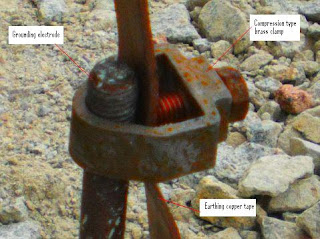
Picture 8 – Earthing copper cable connection to earth rod

Picture 8 above shows another earthing connection inside the earth chamber using the compression type brass clamp.
Observe that the top end of the electrode in this picture does not have the screw thread that is clearly visible in the electrode of Picture 6.
That is because the real top end of the earth rod in Picture was much higher but it was cut to match the expected final ground level.
Copyright http://electricalinstallationwiringpicture.blogspot.com Electrical Grounding Electrode Pictures
No comments:
Post a Comment