Showing posts with label Lightning protection. Show all posts

Friday, March 12, 2010

Lightning roof conductor installation

This post shows a few pictures of an adhesive type of clips for installation of the roof conductors of a lightning protection system to a building’s metal roofing system.

Picture 1 – Method of fixing of air termination conductor network at a roof area


By design, the function of the air conductors is to present at the highest points of a building structure an area that will attract the lightning strikes away from other parts of the building.

The surge current carried by the strike will then be routed down through the down conductors to the earthing or what is called lightning rods at the ground level or the lowest level in multiple basement structures.

You can see pictures of the lightning rods at this post, Lightning earth rod pictures.

=================
RELATED ARTICLES:
Electrical grounding  | Substation main earth bar picturesElectrical Grounding Electrode Pictures  | Switchboard earthing picturesLightning Earth Rods Installation | Temporary Electrical Earthing Pictures | Electrical installation pictures

=================

The Design

The purpose of the design is to create a network of conductors so that no point on the roof is more than five meters away from the nearest conductor of the network.

Where part of a roof structure is raised above general the roof level of a building (e.g. lift motor room), then that part of the structure shall have its own roof conductor network.

This upper air termination network should again be properly bonded to the air terminals of the lower roof, and to the overall building’s lightning protection scheme.

In order to have all points on a roof not more than 5 meters away from the nearest air terminal conductor, the British Standard recommends that a grid of 10m by 20m meter is used.

For high-risk building like explosive stores, the grid requirement is tighten to 5m by 10 m grid.

The Installation

As you can see, in general, the design of a lightning roof conductor network is relatively simple.

Just create a 10 m by 20 m grid (or 5m x 10m) of copper tape throughout all roof areas. Usually that should be good enough for the air termination network.

The vertical terminals (some people call them “vertical finials”) can be installed but as far as I understand it the experts of lightning protection systems have divided opinions about whether the vertical terminals would actually improve the effectiveness of the air termination network.

I know of a government department who forbid the use of the vertical terminals on all their new projects. The reason is simple.

“Why would we want to attract the lightning to our buildings?”

Good point.

Now how do we install the roof conductors? I do not have that many digital pictures on this yet, so I hope what I uploaded below can be of some help to those who need them now.

You will see more pictures on this in the future. The problem I have is that I never thought I would ever need all these pictures of electrical installation works. So I never keep any personal collections of them.

Only now, with the invention of blogs and their related mediums, that realized the mistake of not keeping my own collections of the photographs.

Okay, back to the pictures.

Diagram 2 shows a simple cross section of lightning protection and the roof conductor and Picture 3 shows how a roof conductor is fixed to the parapet wall at the roof level.

Diagram 2 – Simple cross section of a lightning protection system


Picture 3 – Installation copper tape with copper clip


When the roof is a flat concrete roof, the installation of the 3mm x 25mm copper tape is quite simple. The copper clip as shown in Picture 3 is usually good enough. Many engineers prefer a saddle so the copper tape is raised a few millimeters above the surface. That is just a matter of preference.

However, when the installation is on other type of roofing systems, then the method of fixing is usually more difficult.

Problems with the installation of the roof conductor network

With the popularity of the new technology of lightweight all-metal roofing system, questions often arises whether the whole metal roofing system can be bonded to and form part of the lightning protection system without the need for a separate air terminals.

Theoretically "Yes", these metal roofing system scan be used as the air terminal and they have been practically installed to also serve that purpose for a while, even though in many cases the air termination network are still installed as a precaution.

However, the development in the metal roofing system has resulted in the use of very thin roofing sheets that they require some form of metal parts to hold them together and to the roof structure.

The effect is a complete isolation of a sheet from the adjacent one, and to the roof structure.

In these cases, it is necessary to install a separate aerial conductor network

However, fixing the lightning copper tape to roof metal sheets can be difficult or costly to implement. I have had a lot of problems with fixing the roof conductors to metal roofs in the past.

That is the reason I write this post.

I have not been dealing with the installation of the roof conductors for quite a while. However, recently I found out that manufacturers (at least FURSE has it but I haven’t checked with other manufacturers yet) now already has an adhesive type of clips that make the installation of the air terminal network a piece of cake.

The following pictures show the copper tape installation using these clips.

Picture 4 - The adhesive clip installed at vertical position


Picture 5 - Adhesive clip component


Picture 6 - Underside of the adhesive part with adhesive protection


Picture 7 - Installation work of lightning roof conductor network in progress


Picture 8 - Compression joint for 3 mm x 25 mm lightning copper tape conductor
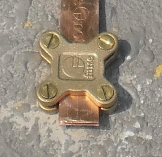


Picture 9 - Coil of 3mm by 25mm lightning copper tape conductor


Copyright http://electricalinstallationwiringpicture.blogspot.com Lightning roof conductor installation

Thursday, March 4, 2010

Lightning Earth Rods Installation

The installation of a lightning earth rod is similar to an electrical grounding electrode. In fact, both are exactly the same thing. There is one small difference though. A lightning earthing need only achieve 10 ohms of maximum resistance, while an electrical grounding may need less than 1 ohms. That is ten times lower resistance, which may mean ten times the number of electrodes that need to be installed.


Diagram 1 – The overall diagram of a lightning protection system


=================
RELATED ARTICLES:
Exothermic welding: Cable to cable connections | Electrical grounding  | Substation main earth bar picturesElectrical Grounding Electrode Pictures  | Switchboard earthing picturesLightning roof conductor installation  | Temporary Electrical Earthing Pictures | Electrical installation pictures

=================

Diagram 2 – A closer view showing the grounding rod chamber and the lightning test point on the wall of the building


Diagram 3 – Cross section diagram of the earthing rod installation


Picture 4 – An existing ground rod chamber


If you have read the other post, Electrical grounding electrode pictures, you will see that this chamber looks the same as the electrical grounding electrode. They are the same materials and construction.

Only the required maximum resistance values are different.

Picture 5 – A grounding rod installation in progress. The earthing chamber is not installed yet


This lightning rod has been connected as a temporary measure. Later a proper and more permanent connection would be done with the chamber installed to protect the electrode connection.

Picture 6 – The earth chamber for the earth rod in Picture 5


This chamber is bigger than the chamber in Picture 4. The sizes of grounding rod chambers vary between 10 in x 10 in to 13 in by 13 in. As far as I know there is no real technical reason for the difference other than that bigger chambers would give more room for the servicing and maintenance work during the life of the installation.

Why should you care about lightning rods?

This is my first post on the subject of lightning protection in this blog. Therefore, I am trying to make it light so that beginners have no trouble digesting the materials.

Another reason for making it easily digestible to casual readers is because every year many people die of lightning strikes whether indirectly or by direct strikes.

I know of a few cases already in my area where a few people died inside their house when the lightning hit the houses.

The worst of these types of incidents that I know was about 4 years ago where all members of a family of four died from a single strike to their house at night.

The point I am trying to make here is that the issue of lightning protection relevant to everyone, not just the lightning specialist or the electrical engineers.

Everyone should be concerned about the dangers of lightning just like the dangers or road accidents.

What Is Lightning?

The lightning strikes come from the clouds that have been charged with static electricity to a very high voltage (i.e. electrical pressure).

These clouds get charged due to the movements and frictions among themselves up in the sky. The electric currents do not flow from the clouds until the air separating them breaks down, that is when it can no longer handle the high voltage difference between a cloud and the earth surface, or between the clouds themselves.


How Is It Created?

When the air breaks down, electric current flows through the air from the cloud to earth and currents in the magnitude of tens of thousands of amperes for each strike are daily occurrences in some parts of the world.

In fact a strike can carry over 200,000 amperes of electric current.

Just consider an electrical overload or a short-circuit in our house wiring. These electrical faults would usually result in the current of only a few hundred amperes. Yet, they can already start fires and cause a lot of damage to properties.

Compare this to the 200, 000 amperes that can be carried by each of the lightning strikes, then we can imagine what kind of damage a lightning strike can do.

Even multiple human casualties are common results from a single lightning strike to an occupied house.

Is your Home Safe From Lightning Strikes?

The question now: Is your home, office or shop building adequately protected against these highly possible attacks from the sky?

Buildings of significant sizes usually have a proper lightning protection system installed. This sort of buildings normally has a knowledgeable management to look after their maintenance.

However, for houses or very small buildings, they may not have the people knowledgeable enough to ensure that adequate protection has been installed and maintained in a satisfactory condition.

How Lightning Protection Works

The conventional design of a lightning protection system is actually an electrical cage. The electrical cage is constructed of electrical conductors or cables interconnected in a network over the roof and the sides of a building.

A few vertical air finials approximately one foot high are normally visible above the roof, and these are connected to and become part of the roof conductor network.

When a lightning bolt strikes, it usually (even though not all the time) strikes these roof electrical conductors. The electrical current will be routed to the ground through a number of down conductors installed uniformly around the perimeter walls of the building or the house at approximately 20 meter spacing.

Once the electrical charge is routed into the ground, the charge must be dissipated into the mass of earth quickly enough.

If not, a high voltage will be developed at ground level and this can damage equipment cause injuries or even death to the building occupants.

The quick dissipation of the electrical charge into the earth mass is accomplished by the installation of steel rods of approximately half-inch in diameter to the depth of a few feet into the ground.

On the ground surface, the top of this steel rods are usually enclosed inside a small square concrete inspection chambers called the earth chambers.

The lightning earthing rods

Seen from the perspective of a building structure, a lightning protection system generally consists of three sections: the aerial conductor network, the down conductors, and the earthing part or what is usually called the lightning rods.

By design, the function of the aerial conductor network is to present at the highest point of the structure an area that will attract lightning strikes away from other parts of the building.

The electrical current carried by the strikes will then be routed down through the down conductors to the lightning rods at the ground level or the lowest level in multiple basement structures.

The purpose of lightning rods

The purpose of the lightning rods is to help dissipate the discharge of the electrical energy carried by up to 200 kilo-ampere of electrical current into the earth mass as quickly as possible.

This is very critical to the performance of the whole system, because a lower rate of energy dissipation will expose a higher risk of injuries or fatalities to human lives (or livestock) due to the presence of a higher voltage gradient on the ground.

Besides, with a slower rate of dissipation there is a higher risk of damage to properties due to flashovers from the lightning down conductors to any ungrounded metal parts nearby.

It is also essential that the down conductors be routed along the most direct path to the ground. Therefore the location of the rods should be beneath the building or as near as possible to the building structure.

Location of the grounding rods

Quite often designers locate the rods at some distance away from the building. This is unnecessary and it may in fact increase the risk of electrocution due to the presence of the voltage gradient across a wider area of the ground.

The Materials

The lightning rods are usually steel reinforced copper rods approximately half an inch in diameter, and driven deep into the ground. In an area free of rocks, they can easily be driven 18 feet or more into the ground.

The Installation Methods

This method of lightning rod installation can give a good reading because the rod surface easily makes an effective contact to the earth mass. Deep driving like this also gives good reading because as the rod is driven into the lower level of soil, it comes into the water level that is not affected by seasonal conditions.

Other Installation Methods

Other methods are also used instead of the deep driven steel rods to provide the best possible contact with the earth mass. The choice depends on the prevailing ground conditions: the soils resistivity and the soil moisture content.

Urban Areas

In urban areas, a few earth rods are usually installed first and looped below ground using copper conductors. Their combined resistance with all rods in parallel is measured and it must not exceed 10 ohms as required by the international standard.

If the combined resistance is above 10 ohms, more rods are driven and connected until the 10-ohm requirement is met.

Isolated Areas

However, in locations away from recent developments, the soil conditions may not be known without actual measurements. Therefore, the soil resistivity tests must be carried out to determine the earthing method most suitable and the extent of the work required.

At times when the soil is sitting on rocky subsoil below ground, a hole may have to be drilled deep down. A depth 100 m or more is not uncommon in more serious cases.

In these situations, a long copper rod is inserted deep into the hole to get the 10-ohm requirement.

In more extreme cases, even this is not enough and soil conditioning agents like Bentonite or conductive cement need to be used.

These compounds are prepared as a slurry or mix, and poured down the vertically drilled hole, creating a lower resistance between the embedded copper earth electrode and the surrounding soil.

The cases that require this method of lightning rods installation may not be very common. However, it does happen.

An example may be a district gas pressure reduction stations, or other similar type of plants.

Combine all the grounds

Finally, it should be remembered that a combined earth with other services can much reduce the overall cost of the grounding for these separate systems.

This is also necessary to prevent side flashovers from the lightning conductors.

In the end it may well be that the lightning rod network is the shared earthing system for all services.

Check out the following posts for more pictures on grounding rods and other issues:

Electrical installation pictures;
Temporary electrical earthing pictures.


Copyright http://electricalinstallationwiringpicture.blogspot.com Lightning Earth Rods Installation