Showing posts with label Building services. Show all posts

Sunday, March 6, 2011

M & E Coordination

The few pictures that I show in this post is a demonstration of what can happen when proper coordination drawings are not produced prior to the commencement of the mechanical and electrical services installation in a multi-storey building.

Picture 1 – Improvised installation of electrical trunking, air-conditioning ducts, fire protection pipe work and a floor beam


===== RELATED ARTICLES:

===========

Somewhere among my previous posts, you can find examples of good coordination between the mechanical and electrical services installation.

However, here I wish to show you the opposite side of it. The above is not the worst case examples. I have plenty of pictures showing much worse scenarios which I will show you in future posts.

A reminder for the beginners in electrical installation works: Learn from the mistakes that other people have done and plan your work accordingly.

This is a very expensive lesson if you have to learn it from personal experience because rectifications, relocation or corrections in large installations can be very expensive and time consuming.

I do not plan to make this a long article. Regular visitors to this blog may have noticed that I have not been posting for quite a number of months.

A few have been asking me to continue posting articles and adding more topics.

So today I am back and you can expect to see some more pictures of electrical installations, good and bad.

There are readers who condemned a few of the pictures that I use to explain something.

They seem to have the opinion that using pictures with bad installation practices is like promoting bad installation practices.

With all due respect to their experience and expertise, I beg to differ on this matter and I think many would agree with me.

I also wish to remind the readers that none of the electrical installation works published here is my handiwork, whether the good ones or the bad ones. I did not do the wiring work; I did not do the trunking installation, etc.

I might have been the inspector with the responsibility to inspect or audit some the installation works.

However, when I show a picture, it does not necessarily mean that I say “this wiring work is a good example”. Or it is bad, unless I specifically say so.

It only means that there is something that the readers can learn from the picture.

Please bear in mind that different readers may learn different lessons from one single picture.

One of the primary objectives of this blog is to educate common people in how electrical installations work in real life. That is why I use “real” pictures.

In real life, the “real installations” (such as one’s own house wiring) are often “not that neat” and not that pretty.

It is very easy for me to show you pictures of neat and orderly house and office installations. I work in the construction business and I have tons of pictures of neat installations like that.

However, people often find it hard to understand the actual wiring in their own house or their own small offices because in most cases the wiring works are not new. They have been modified and they have been tampered with by people who either didn’t know enough or didn’t care enough about safety, or he tried to make the wiring works at a very low cost.

Whatever the reasons for the bad practices, the occupant who inherit the unit is faced with a wiring “system” that is hard to understand and is full of bad practices.

It is for this very reason that I use these pictures to explain how the wiring works. They are “real”.

That is all I have time for today. Enjoy the pictures and see you again in the next post.

Picture 2 – Electrical trunking and air-conditioning ducts


Picture 3 – Sprinkler pipes and trunking


Picture 4 – Telephone trunking, electrical and aircond duct


Picture 5 – Sanitary piping and domestic water pipes above electric trunking


Picture 6 – Sanitary pipes above electric trunking


Picture 7 – Trunking below sprinkler pipes


Picture 8 – Trunking below water piping


Picture 9 – Water pipes above trunking


You can see more pictures of electrical installation at this post, Electrical installation pictures.

Copyright http://electricalinstallationwiringpicture.blogspot.com M & E Coordination

Friday, April 16, 2010

Building’s electrical rooms layout

During the design of an electrical installation for a building, spaces that are required as electrical rooms need to be provided for very early in the planning and design process.

I will try to present this in a form of a few basic concepts so that non-electrical readers can benefit from it.

There are also a few diagrams at the end of this post, but I do want to go too technical here as this may turn off the non-electrical readers.

If you need a more technical discussion, I will send a few posts of electrical substation layout and design in future.

=================
RELATED ARTICLES: | Substation rooms layout diagram |  1600 kVA Transformer Pictures | Cable ladder pictures  | Electrical installation picturesFire Riser Rooms
=================

Sources of electrical supply

Two (or sometimes three) sources of electricity are normally required in high-rise buildings:

1) The normal mains supply from the electric supply authority or the local electricity supply company in some countries.

2) The standby or emergency supply for the standby electric generators. In most situations, this supply is not an option, but a mandatory requirement for buildings that exceed a certain size.

3) The uninterruptible power supplies, or commonly called UPS. This is only needed in certain types of office buildings and in some hospital buildings.

Voltage level of the incoming supply

The normal mains supply taken from the authority may be taken at HV (high voltage, normally 11 kV in this country), or LV (low voltage, 415 Volt, three-phase four-wire).

Whether it is the LV or HV supply depends on the size of the maximum electrical demand to be expected of the planned building when it is in full operation.

It also depends on the effects of voltage drops and the level of voltages that are currently available from the supply authority.

Authority’s HV room

When the incoming supply is HV, the authority usually only require a HV switch room to be built and handed over to them. This is where they house their high voltage switchgears and other equipment.

The location of the Authority’s HV room

The location of this room must allow for easy access by the authority’s maintenance people and it should not present an inconvenience to the occupants of the buildings or disrupts the building’s normal functions and operations.

(Separate meter room: At times, the local office of the electricity supply authority requires that a small meter room be provided and handed over to them. This is where they house the meter panel.)

Electrical distribution cables from the authority’s distribution network in the area will be tapped and looped to the HV switchgear panels in this room. They usually install a series of HV panels here.

Then from one of the HV panels, a supply feeder cable will be laid and connected to the consumer HV room.

Consumer HV room

A consumer HV room is generally a repeat of the authority’s HV room. The equipment and switchgears located in them are also similar.

The purpose of the consumer HV room is to house the equipment that are essential to the safe and proper handling of the electrical high voltage supply received from the authority’s HV room.

If the building management need to switch off the high voltage supply for some reasons, then this is where they do it.

Among the reasons may be if the transformer is faulty and need to be serviced ar checked.

Another reason may be if the transformer room is located at a separate location and the high voltage cables to the HV switchgear is by cables buried underground. Sometimes an excavation need to be carried out very close to the cable location that a complete shutdown to the supply carried by the cables is necessary.

The third scenario might be if the main low voltage switchboard (the electrical panels that receive the low voltage currents directly from the transformer) need maintenance or repair. Then the only way to make the main switchboard completely dead is by turning off the supply at the HV switchgears inside the consumer HV switchroom.

Can we turn off the supply by switching off the switchgears inside the authority’s HV room?

No, we can’t.

The room and all the equipment inside them are legally theirs now.

By transferring the HV electrical room to the authority, the building owner are actually required to sign some form of an agreement to transfer the ownership of the room to the electricity supply authority, or to lease it to them for a duration of 99 years I think.

It is like an embassy building in a foreign land.

Likewise, the supply authority is not allowed to freely access the consumer’s HV room or the equipment inside.


Metering CT

Buildings taking supply exceeding a certain amperes require the use of a set of CT’s (current transformers) in order to measure the energy consumption. The contractor of the new building will have to provide these CT’s.

However, the new CT’s also need to be sent for calibration and certification by the electric supply company before installation.

After the calibration, the CT’s are installed inside the consumer HV panels. A set of wiring are then installed to connect these measuring current transformers to the authority meter panel inside the meter room.

Authority’s transformer room

Sometimes during the negotiations on the application of the supply, the authority may require that a transformer room is also provided and handed over to them together with the HV room.

Usually this happens when there is no suitable site available for their substation in the vicinity of the area, such as when the planned building site is at a congested area of towns like the city center.

When transformer room(s) is required, the authority electrical substation would be a complete substation, not just a HV room.

This means that the substation may also be used to supply other buildings and properties nearby.

Distance from Authority HV room to Consumer HV room

As mentioned, the HV feeder cables that will carry the electric current to the planned building will need to connect to the consumer’s HV switchboard in the consumer HV room.

Part of the cost born by the authority in order to give supply to the new building are usually charged to the consumer (in what is usually called a “contribution fee”) and need to be paid before the authority commence their installation work.

Therefore, the nearer the consumer HV room is to the authority HV room, the shorter the HV cables that need to be laid and the lower the cost of the cables that need to be shared by both parties.

So in many cases, the consumer HV room needs to be nearer to the authority’s HV room.

In construction projects where the land space is limited such as building projects, it is highly recommended to locate the HV electrical rooms as close to each others for another reason.

Areas where high voltage equipment and cabling are installed need to be controlled as a restricted area. Locating the HV room near each other would make control easier and the restricted area would take less space.

Consumer’s transformer room, LV room, standby generator room and UPS room

Other than the HV room, the consumer also needs a transformer room, the LV room and the standby generator room. When a large UPS supply is used, then a UPS room may also be needed.

LV room and transformer room to be as close as possible

The consumer transformer room and the LV room need to be as close to each other as possible in order to minimize the voltage drop.

For every meter of extra distance between these two rooms, a significant cost needs to be spent to overcome the voltage drop to an acceptable level.

The cables used to carry the low voltage electrical supply also are usually of very large diameters.

Large diameter electrical cables are very difficult to maneuver and bend around corners and tight areas.

Keeping the two electrical rooms close to each other effectively reduces the bends needed of the electrical cables.

Supply intake at LV

If the electricity supply taken from the authority is LV (low voltage), then they will require a HV room and a transformer room to be provided. The two rooms must be situated adjacent to each other although sometimes they accept that the HV switchgear and the electrical transformers share the same room to save space.

The consumer is also required to provide a main switchroom adjacent to the transformer room. The standby generator room also needs to be near the main switchroom.

However, if the electrical energy required by the building is less that about 300 KVA, no electrical room is required to be prepared and handed over to the electrical authority.

They will tap off the supply from a nearby existing electrical substation or tap it off from an existing low voltage distribution network.

It is for this reason that some property developers submit their application of electric supply in stages with each stage requiring not more than 300kVA.

All the above electrical rooms are needed so we can receive supply from the public mains.

However, there is the second type of electrical supply in a building operation, which is the standby generator supply. I will not talk about the third type, the UPS supply (uninterruptible power supply) today because only certain types of buildings use it. I will address that topic in a separate post.

Standby diesel generator room

As I said earlier, no building exceeding a certain size or a certain height is allowed to be operated or occupied without some form of a standby emergency power.

The “emergency” here means when the public electrical supply is suddenly not available.

It also means a fire situation because a normal electric cable would fail under fire and the fire fighting equipment would need “emergency” power so the firemen could use them.

Now, this standby diesel generator and all its ancillary equipment need a room to house them in.

However, the electric generator is a bulky and noisy machine. It also produces very strong vibrations that can be transferred to the building walls and structure.

Therefore, a room for this electrical generator need to be specially designed and the room location need to be purposely located.

If you are given the freedom to make a decision, make a small separate building to house this noisy electrical generator, preferable somewhere hidden behind the main building.

Then build up all other main electrical rooms that I described earlier around the generator room.

If you start that way, you will have no problem later when the issues of noise level, engine exhaust, radiator exhaust, fresh air intake, maintenance access route and fuel storage tank come into play.

That is usually the time when the architect and the building owner start asking whether we can exhaust the radiator hot air at the third floor level 50 meters away.

Locations of substation rooms

The actual locations of the electrical rooms at the building complex are a major factor in the design of all types of electrical installations. There are a few major requirements that must be taken into account when deciding on the locations for these rooms.

1) They should be located inside the buildings, as near as possible to the load centers.

2) The electrical rooms should be as near as possible to each other.

3) The rooms need to be accessible by maintenance vehicles and maintenance people for purposes of installation, operation and maintenance works. This should be possible without disrupting the normal operation of the building.

4) They should be accessible by heavy vehicles during installation and when replacement of heavy equipment is necessary.

5) They should be adequately ventilated.

6) All electrical rooms should be adequately secured from possible disasters like flood, or even vandalism.

The above electrical rooms are in the category of substation rooms. For aesthetic reasons, layout of the buildings can be made such that the electrical rooms are located at a separate building adjacent or hidden behind the main buildings.

In fact, it is even preferable for the rooms to be secluded somewhere as long as all the above criteria are met because that would reduce the risks of interference to the functioning of the electrical system including accidents and even vandalism.

However, there are still a few more electrical rooms, which are needed for proper and efficient operation of an electrical installation in all buildings especially those of the multi storey and high rise types.

Other electrical rooms:

1) Electrical service ducts

Electrical service ducts or electrical riser rooms are used to house the submain cables that carry electricity supply to the upper floors of a building, which include the plants and machines at the roof top such as the chiller plants, cooling towers or the lift motor rooms.

The rising mains that supply the lateral distributions on individual floors are also located in these vertical ducts.

Often these concrete vertical ducts are as large as a small room. That is why it is often called electrical riser rooms.

The electrical riser rooms do not have to be stacked vertically like the toilet risers or wet stacks.

However, it is better to do so as it would minimize turns and sharp bends that can damage the cables.

Riser rooms stacked straight up from the lowest floor to the highest building floor would also minimize the length of the electrical cables required.

Minimum cable length not only reduces the cost directly. Longer route of an electrical cable run may cause too much voltage drop along its length that may require it to be changed to one or two size larger.

Larger cables cost more money.

2) Individual floor electrical rooms

Each individual floors of significant size will usually need at least one dedicated electrical room to house the electrical distribution equipment for that floor.

However, sometimes the vertical service ducts may be able to fulfill this function in which case a separate electrical room may not be necessary.

The architect may then need to make these service ducts bigger to give them enough space for proper operation and maintenance.

The electrical rooms at each floor house the electrical panels that serve the final circuit wiring.

Therefore, they should be as close as possible to the load center of the area that it serves.

Very tall buildings

If the planned building is very high (let’s say a 40 storey office building), or in cases where heavy loads are located at higher levels of the building, it may be necessary to provide substations at the higher levels of the building.

For the 40-storey office building, an 11/.415 kV substation may be necessary at one of the upper floor. It may be located at twentieth floor, for example.

All the electrical substation room spaces as explained earlier will then need to be provided except the authority’s electrical rooms.

The floors of this substation would then need to be specifically designed by the appointed structural consultants to handle the loads of all the substation equipment.

Electrical rooms must be planned for early in the design stage

The above requirements need to be planned for at the early stages of the design and coordinated with the architects and structural engineers.

In many projects, the room spaces and their locations as requested by the electrical engineers are subject to “negotiations” with the architects and structural engineers, not merely technical coordination and interfacing.

But that can turn to be a controversial subject so I think having a separate post on it will be better.

That is all I want to say on the electrical rooms today. I will continue again in the next post.

However, there are a few diagrams of electrical room layout that I think can help some readers make more sense of what I described above.

Diagrams of electrical rooms:

The first few diagrams show the core layout of a nurses' apartment building. The core layout means the layout of the building services infrastructure with the lift core at the center.

When the architect lays out the components of building services, this is what she need to place first.

Since this building is an eight storey building, I showed here the layouts of a few floors. This will help you see how the electrical rooms and the rooms of a few other building services go up the building floors.

I will not comment much on these diagrams today. Just observe the diagrams and you will be able to see the logic behind them.

Diagram 1 – Ground floor layout of building services


I will explain a little bit here to help the freshies get started.

ELEC – electrical riser room (I have uploaded some pictures of electrical riser rooms at this post: Electrical busduct installation pictures. Click the link and you can see what electrical rooms look like in an actual installation).

MATV - the riser room for the MATV (master antenna television) system. If the building has a CCTV (closed circuit television) system, the riser cables will run inside this riser shaft to connect to upper floors of the building.

In many building design, a single riser shaft is used to run all the ELV (extra low voltage) services to the upper floors.

(Note: When all the riser rooms at each floor are stacked up vertically straight up, then it forms a shaft. So it is called a riser shaft.

Put in another way, a long time ago when the ancient builders found out how to build a building with multiple floors one on top of the other, the riser started as shaft or a vertical wooden duct.

In order to make it safe for working inside it at each floor, they extended the floor into part of the riser. Then it became like a room. So it was called a riser room.)

TEL – for telephone cables and equipment.

DR – dry riser. A building exceeding a certain height is required to install vertical pipes with inlets at the ground level. These pipes will be used to pump water from fire engines to the upper floors so the firefighters can fight fire.

If the building height is even higher, dry pipe riser would not be accepted by the fire department. A wet riser system would then be required. This is the same piping as the dry riser but with water tanks to store water and sufficient number and horsepower of pumps to always keep the water under sufficient pressure in case there is a fire in the building.

WATER – Water is not available here. Just pipes that carries domestic water. Designers just label it WATER as a short form for COLD WATER.

ON CALL – You would only have this at residential buildings for hospital employees. They have a communication system that can call the employees on standby when they have to report for duty immediately.

The red rectangular symbol inside the electrical riser is the electrical panel. You will find one or more electrical panels at the upper floors also.

Diagram 2 – First floor layout


Diagram 3 – Sixth floor layout


Diagram 4 – Layout for seventh and eighth floor


The eighth floor is the highest occupied floor inside this building. The floor above is just a roof level that is normally used to locate some mechanical services and fire fighting equipment and plants.

If there is a centralized air conditioning system in this building, then the cooling tower may also be located here.

Diagram 5 – 
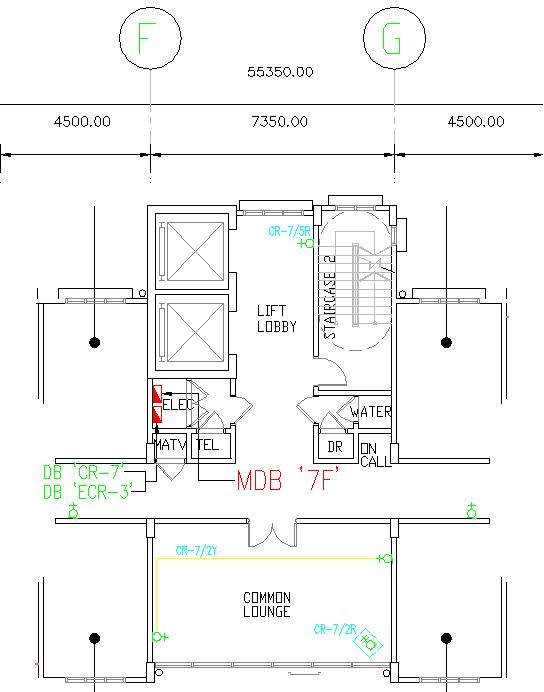
Closer view of the electrical riser room and the Main DB


I zoom specifically to this area to show you what is supposed to be inside the electrical riser room.

Observe the legend for the upper electrical panel symbol.

The symbol legend MDB ‘7F’ stands for Main Distribution Board No 7F. “7F” means Seventh Floor.

The lower electrical panel symbol represents two electrical panels, each with labels DB ‘CR-7’ and DB ‘ECR-3’.

So there are three electrical panels inside this riser room.

I will explain why one of the DB’s is called Main DB when I touched a little on the single line diagram of the MDB in Diagram 7 below.

Diagram 6 – Layout for roof level


Diagram 7 – The single line diagram for individual apartment’s electrical panel


The main electrical supply cables to the upper floors are run inside the riser shaft.

The electrical panel for each individual nurses’ apartment is inside the apartment unit itself.

Diagram 7 above shows a typical single line diagram of the wiring for each apartment.

Now in order to get the electrical power, each of these electrical panels needs to be connected to the riser cables.

There are eight apartment units at each floor. So there would be eight sets of tap off unit attached to the riser cable inside the electrical riser shaft.

This quantity of tap off units can present many maintenance problems during operation of the building.

Moreover, the cables connected to the tap off unit also need to be protected with a circuit breaker. That means we need a panel to house the circuit breakers.

With eight units of apartment needing supply, we might as well install a large electrical panel to house all the circuit breakers to protect all the supply cables to the eight apartments.

Then we can use a busbar to supply all the eight circuit breakers.

This way only one set of tap off unit is required, which is to supply the distribution busbar inside the panel.

This is what is represented by the schematic single line diagram in Diagram 9 below.

Diagram 8 – Single line diagram of Main DB


With the entire individual apartment DB’s taking supply from this electrical panel, it is called Main DB or MDB.

Don’t let all these names confuse you. Some would call this Main DB a sub-switchboard, or a floor DB.

It is just an electrical panel upstream of the other in the hierarchy of the electric power distribution system of the building.

Okay guys. I would love to continue this further as I have not yet touch on the diagrams of the substation rooms.

It’s already 3.30 in the morning. So I will continue with this in the next post, okay.

Copyright http://electricalinstallationwiringpicture.blogspot.com Building’s electrical rooms layout

Saturday, April 3, 2010

Feeder pillar single line diagram

Today I will show the readers a simple schematic diagram of a compound lighting feeder pillar. It is for those who need to know a few basics of a compound lighting system in order to carry out other tasks such as architectural landscape design and costing works, etc.

There are also a few pictures of feeder pillars so the single line diagram will make some sense. If you need to allocate some space for the feeder pillar plinth, then I have already uploaded a few diagrams towards the end of this post. They should give you enough information to solve the technical problems.

Diagram 1 – Single line diagram of a small feeder pillar for compound lighting


================ RELATED ARTICLES: Electric Cable Drum Pictures | Underground street light cablesWeatherproof 13A switched sockets | Metal-clad socket outlet | Compound lighting storage yardCompound Lighting Installation Pictures | Bollard light pictures | Feeder pillar hazard pictures |  Compound lighting foundation size  | Electrical installation pictures Architectural Lighting
================


A feeder pillar single line diagram is similar a house electrical panel schematic diagram with the addition of an automatic time switching circuit added.

In the single line diagram, the time switching circuit is the circuit portion towards the top left corner of the dotted rectangle box. The sub-schematic is shaded into lighter grey.

Diagram 2 – Timer switch circuit


There are three items I wish to highlight to readers at the time switching circuit: the time switch, the contact coil and the “SWITCH BY PASS”.

The TIME SWITCH

First, the time switch. This is drawn with a symbol of a circle with the “TS” letters inside it.

A time switch is a component that is common to all street lighting and compound lighting. Its purpose is to eliminate the need for human actions to turn “ON” and “OFF” the lighting at the intended operation hours.

For example, the external carpark of a shopping complex may need to be lighted up at 7 every evening and be turned off at 3 A.M.

So this ON and OFF times can be set at the time switch inside the feeder pillar.

A human operator may miss the exact time one day, which can leads to complains by customers, but a machine would not forget. They may break down, but a properly cared machine can be much more reliable than human most of the time.

In large installations, even indoor lights are sometimes installed with similar automatic timers. It is not just for good service, but also to reduce operating costs as the setting of the timer can be authorized to only selected individuals of the organization.

One hour of delayed switching off the lights every night can mean significant additional dollars monthly on electricity bills in large installations.

The SWITCH BY PASS, or MANUAL BYPASS SWITCH

Another important component here is the normally open switch that is labeled SWITCH BY PASS in the single line diagram.

In many drawings, it is called MANUAL BYPASS SWITCH, which I think is more appropriate and more accurate. But one of my draughting lady tends to prefer SWITCH BY PASS label so much that I need to let her have her own way.

The manual bypass switch is used for maintenance or trouble-shooting works. It simply bypass the time switch to ON or OFF the external lighting or street lighting.

For genuine beginners, observe that the bypass switch is connected in parallel with the contacts of the timer relay (Diagram 2 above). With this configuration, either contact in a closed position would energize the contact coil and turn on the external lights.

Often the switch is also the key-operated type so that the ability to bypass the timer can be restricted to only authorized individuals.

The contact coil

This is the third component in the time-switch circuit.

The load currents to the lighting cables are usually higher than the current that the timer contacts can handle. Therefore, another coil with heavy current contacts need to be provided to switch the heavy currents.

That is the purpose of the coil with a symbol of the circle with the “C” in it.

Observe the dotted line connecting the coil to the three contacts at the lighting load circuit.

That is all I wish to say on the timer switch circuit today. For electrical-based readers, the above explanations are never necessary. However, for no-electrical readers, these details on the schematic diagram would probably confuse many of them

Now let’s go through a few more components inside the feeder pillar cubicle that may confuse the readers from understanding the simple single line diagram.

The cubicle lighting

Towards the right edge of the dotted rectangle, there is a fuse labelled “20A SPN S/F”. You may not see this extra component inside a normal distribution board.

It is used to supply a fluorescent light inside the feeder pillar. As you know, the feeder pillars are installed outside. Any problem to the compound lighting would probably be noticed at night, when the lights are supposed to function.

Because of that, maintenance, trouble-shooting or repair works need to be done in the dark outside. The lighting from the compound lights would not be enough for work inside the feeder pillar. Additional light lighting is needed and that is what the fluorescent light fitting is for.

The socket outlet is also provided for the same purpose (i.e. to operate the tools for the maintenance work).

These are the accessories for the street light feeder pillar or compound lighting feeder pillar.

The timer switch circuit is actually a control circuit.

Other that that, the circuit schematic is almost similar to a simple house schematic.

The main schematic

Now let me give a short brief on the main schematic, the power circuit of the system.

As explained above, the dotted line rectangle represents the physical area of the feeder pillar cubicle.

Components and symbols located inside the dotted rectangle means they are located inside the metal cubicle. That is how to interpret an electrical diagram of this type.

The electric supply is taken from the Consumer Main Switchboard as shown at the lower part of the diagram.

A short introductory brief on armored electric cables

One length of underground armored cable is used. Underground means the cable is installed inside the ground about 3 ft below the surface.

Armored cable cost much more because of the steel wire armor protecting the cable from physical damage. The letters SWA in the cable tag “XLPE/SWA/PVC” is an acronym for “steel wire armor”.

“XLPE” at the front means the insulation of the cable conductor. When we say a cable, the terminology is actually not precise enough.

In this case, inside the incoming supply cable there is actually 4 inner cores each with an electrical insulation. Therefore, each of the four insulated inner cores (the inner core is usually made of either copper or aluminium) is a complete electrical cable by itself.

The four of them are bunched together to make it easier to run and it can reduce the cost. We can actually use 4 independent cables instead of one cable with 4 inner insulated cores.

The XLPE label mentioned above indicates the type of insulation of each of the inner cores.

When these cores are bunched together in a bunch like these, an outer insulation is again extruded or layered over the whole bunch, making it look like a single cable. It is actually 4 cables that are bunch together.

The outer insulation is called outer sheath.

If this cable is to be installed underground, it is always better and always considered necessary to provide something strong over the cable in case an excavation work accidentally hits it.

That is why the steel wire armor wrapped around the cable spirally all along the cable length. The armor protects the cable physically.

Then in order to protect the armor against corrosion and other degradation, another layer of insulation is applied over the steel wire armor. Most of the time, it is of PVC (poly vinyl chloride) materials.

That is the label “PVC” on the right of the cable tag.

I did not finish the XLPE part, did I?

What is XLPE?

The XLPE is just like the PVC, but is more expensive and of better quality. That is why it is used only at the inner core of the cable. The PVC material can be used instead of the XLPE, and it will work just fine.

But with XLPE, the inner cores can usually carry higher current for the same inner core size.

I know many readers already now this, but I always wanted to put it down somewhere so I can just give a link whenever an issue requires a further explanation on this cable topic.

What is 1 – 25 SQ. MM. / 4C?

“4C” – I just explained above, the 4 inner cores. If there are 5 or 3 cores inside, then it would have been 5C or 3C accordingly.

“25 SQ. MM.” – I mentioned about the size of each inner core, the copper or aluminium material underneath the XLPE insulation. This is the size. It is always in the form of net or real cross-section area. This means if an inner core is constructed of several smaller cylindrical copper wires, then the total cross-section area of those individual wires is taken and used to indicate the size in square millimeters.

I am following the British or European Standards here.

“1 – “ … well this mean one length of the 4-core cable is used here. We can use 2 lengths which will give us 8 cores of same sizes. They are installation conditions that may force us to do that, which is a more advanced topic. In that case, it would have been written like this:

“ 2 – 25 SQ. MM. /4C XLPE/SWA/PVC”.

That is all about the incoming cable.

The feeder pillar isolation switch

“60A TPN MCCB” – this is the isolation switch. The type of switch used is MCCB (moulded case circuit breaker).

So this switch is also a circuit breaker. It can automatically switch OFF when there a fault inside the feeder pillar cubicle or the cables going to the light poles.

You can actually use a switch and a fuse instead of the MCCB. That is the protection used to supply the cubicle fluorescent light explained above.

The outgoing circuit protection

Going downstream of the power flow path, you can see the outgoing circuit breakers (i.e. 20A SPN MCB) that are used to protect the cables going out to the light poles.

Six MCB’s are installed here.

Three are spares however. No cable is connected to the spare MCB’s even though there is a red line drawn to each one of them. This is the practice when drawing these types of electrical diagrams.

Each of the three MCB’s that are electrically loaded (they have electrical loads i.e. the lights connected to their outgoing cables) has 6 compound light fixtures connected to it.

Each of the fixtures is 70 watt. So we have 6 x 70 = 420 watt connected to a 20A circuit breaker. That is how to read the diagram.

The type of the compound light fitting is HPSV (high pressure sodium vapor).
(UPDATE: A low-pressure sodium type of street light or compound lighting would give you the yellowish light like those seen on the highway. Not a nice color but this type is very energy efficient.
But the high-pressure sodium vapour (HPSV) type that is used here has a good "color rendering". This is the terminology lighting people use to say that the colors produced by a lighting fixture allow human to distinguish different colors easily and correctly.
The low-pressure sodium lamp as mentioned earlier is very energy efficient. However, the yellowish color that it produces have a very poor "color rendering". Have you ever seen the color of your own skin under one of these lights at night? )

The number of lights connected to each outgoing circuit is quite standard for compound lighting. Most installations only connect 6 lights to a circuit regardless of the MCB rating or the rating of the light fixture which usually varies between 70 watt to 250 watt..

So you can actually know how many outgoing circuits you need once you know or estimate how many lights would be installed inside the building compound.

Now let us look at a few of the feeder pillar pictures

Picture 3 – Feeder pillar for compound lighting


This is for a compound lighting system at a public building. Notice the concrete plinth that it is sitting on.

Here there is also an additional power socket installed but it is located outside the cubicle. Therefore, it has to be of a weatherproof type.

Picture 4 – Outdoor power socket


When you install electrical equipment outside of a protected room, under the rain and hot sun, it need to be of a weatherproof type.

Electric voltage inside an electrical equipment and appliance is very dangerous. It can easily kill people.

Every knows that. But when it is installed at a location where there is a possibility of water seepage into the enclosure, then the equipment become extremely dangerous.

That is why when we say weatherproof, the design, manufacture and installation must comply to a certain criteria and quality standard.

The category of degree of waterproofing is graded by what is called IP rating.

Picture 5 – Weatherproof socket IP rating


The 13A power socket here is rated as IP 66. The letter IP stands for Ingress Protection. I think that was how it came to be.

The first number after IP is the grade of protection against ingress is dust and solid objects into the enclosure.

The second number shows the class of protection against harmful ingress of water. The number 6 in this case means that the outdoor socket unit has been designed and manufactured to withstand against water jets to the unit from any angle.

This is important because being installed at a landscape area there are possibilities of strong water jets when the caretaker is watering the landscape garden.

A cleaning work of the compound area after parties and functions may also expose the unit to water jets.

IP Rating of the feeder pillar metal enclosure

I have spoken of the need to waterproof the outdoor socket outlet. The feeder pillar metal cubicle is even more important to be waterproofed.

I did not take the photo shot at the manufacturer label of the feeder pillar. However, I think the IP rating of the above feeder pillar would not be less than IP 56.

This means that the protection against the ingress of water is of the same grade as the 13A socket.

However, the protection against the ingress of dust and solid objects is probably at grade 5, which is one step lower than that for the socket.

At grade 6, the enclosure would not permit any ingress of dust at all. But at 5, some very small dust particles may still be able to enter the feeder pillar enclosure without any harmful effect to the operation and quality of the components and installation inside the cubicle.

The photographs above was taken of an existing feeder pillar for a compound lighting. The other 2 more below are from a new installation that is still in progress.

Picture 6 – New feeder pillar installation in progress


You can see that the underground cables to and from this feeder pillar are not yet terminated.

This unit seem to be much bigger than then existing one shown above. However, that does not necessarily mean it carries more electrical load or anything.

It only means the cubicle design provides more space inside for the access to the components and parts. Usually a bigger unit cost more even if the schematic design used to manufacture them is the exactly the same one.

Picture 7 – Cable entry to the feeder pillar


For readers who are looking for some details on the construction of the feeder pillar, bellow is an example. These 4 diagrams provides you enough measurements to locate the unit precisely at a tight space in a building compound.

With the single line diagram in Diagram 1 above, you can even get a pretty accurate estimated cost from the manufacture and supplier if you allow them to use their standard parts and components.

Diagram 8 – Feeder pillar front view


Diagram 9 – Interior component layout


Diagram 10 – Side dimensions


Diagram 11 – A section showing how the components are to be arranged and routed


Copyright http://electricalinstallationwiringpicture.blogspot.com Feeder pillar single line diagram

Thursday, April 1, 2010

How to install overhead projector

Readers who are looking for information how to install a motorized overhead projector to the ceiling may find the following pictures useful.

I will not write much here because there is not much to write. A picture says a thousand words.

The methods of installation mounting used are just standard methods. I just thought there are people out there who need to know how to do it or how it is done for one reason or another.

Picture 1 – Motorized overhead projector mounting


===== RELATED ARTICLES:

===========

This mounting has been done for my approval some time back. The location was inside a large (about 100 pax) meeting room for a high rise office block.

The unit in the picture was a mock-up unit so I could check it. Actually the sizing of the mounting bolts, the hanger rods and all metal works were all done by guesswork by the contractor.

But they oversized everything so much it made me speechless. The stingy contractor became very generous that day.

However, I knew the projector unit to be installed was very expensive. So I guess the contractor did not want to take any chances.

Notice that two hanger rods were used. They were larger steel pipes actually. Each was welded at the top to a thick steel base plate with four mounting screw holes (see Picture 2).

Picture 2 – Hanger rod base plate


The lower end of each hanger rod was also fixed with a similarly welded base plate which is used to fix the projector mounting plate (Picture 3).

Picture 3 – Bottom base plate


Picture 4 shows the whole assembly for one hanger rod. I separate it here so everybody can understand.

Picture 4 – One hanger rod assembly


The projector rack unit in picture 1 is what people call motorized projector.

It is actually not a motorized projector. It is the projector rack that is motorized.

You can put any projector there as long as the projector size can fit into the rack size installed.

The motorized rack is used so that the projector unit can be concealed into the ceiling when not in used. I took a few pictures of the completed work where you can see that the whole unit is totally recessed into the ceiling but I do not seem to be able to find them.

I will upload those photos later.

I have said enough about the mounting method I think. Notice also the cables hanging around the projector rack in Picture 1. Those are the rack’s power cable and the temporary supply cable to demonstrate the operation of the mock-up.

I approved the sample and about thirty unit of these motorized projector units were installed throughout the office building.

Picture 5 – Closer view of the motorized projector rack


Picture 6 – Another angle of view


See this post, Electrical installation pictures, for more pictures of electrical building services.


Copyright http://electricalinstallationwiringpicture.blogspot.com How to install overhead projector

Tuesday, March 30, 2010

MATV antenna bracket pictures

I have a few installation pictures of MATV antenna brackets. In fact I have quite a number of pictures on the installation of other building services such as the public address system, the firemen intercom, audio visual and conference system, etc.

=================  RELATED ARTICLES: MATV trunking riser  |  Lighting flexible conduitsA simple electrical installation | Electrical socket extension unit  | 1- Phase ELCB connection pictures  | Bare fluorescent light pictures  | Recessed down lights installation  | Bollard light pictures  | Light switch installation pictures  | Home wiring pictures  | Electric Meters  | Electrical Grounding Electrode Pictures  | Most Basic Principles of House Wiring |
=================

All these are part of the electrical contracts in a building construction works.

They are classified as building services together with the cold water supply, the fire protection sprinklers, etc.

When I started this blog, I wanted to make it specialized in only electric supply systems.

However, I have also always asked myself what to do with all the pictures on the ELV (extra low voltage) systems and telephone works.

It has been such a waste. Those pictures can be of use to many people such as those whose need real installation pictures of the systems in real construction works.

Even I myself was having such needs during my early days in the electrical world. Of course, now anyone can search among the tens of thousands of the manufactures’ and suppliers’ websites specialized in these systems.

However, often we only find nice pictures and often we do not want nice pictures.

We want the real construction pictures, pictures that are not biased towards any particular supplier or manufacturer.

For this reason, I am expanding the scope of this blog to also include the installation pictures of building’s extra low voltage (ELV) services and telecommunication systems.

In the future, I may even include building’s ICT systems.

After all, the title of this blog is “… installation pictures”. The internet search engines should not be confused about the content of this blog, I think. We will see.

Now let’s get back to the pictures.

I will not be writing much on this. My specialty is not on these technologies. I only have some experience with them, including design (aka system integrator) and installation supervision.

Therefore, I will only be going through the pictures very briefly when it comes to the ELV services and telecommunication systems.

Picture 1 – Installation of MATV antennas


I apologize if you need to look closely at the picture to see the antennas. I should have taken the photographs before they started work on the roof installation. The green color of the construction safety nets seems to have disturbed the clarity of the antenna image in the picture.

However, Picture 2 below shows the antenna brackets quite clearly.

Picture 2 – Antenna brackets mounted to a roof wall


Well, there is nothing special with the brackets here. Just similar to the types that you may have at home.

However, observe that stay wires were used to add stability to the poles. You may not have the stay wires at home.

Picture 3 – Closer view of a bracket


Picture 4 – The flexible conduit connection between cable trunking and the rigid steel conduit


Below is an example single line diagram for an MATV installation at a multi storey building. I hope it will help “genuine” beginners place where the antennas are located in the overall system of the MATV installation.

It was part of a draft proposal for a turnkey project many years ago. So it is simple enough and easy to understand.

It was also the first AutoCAD soft copy file that I found in my old archive when I started digging for a schematic diagram to complement the above MATV pictures. I would not want any beginner reader to leave this post confused.

A list of the symbols used in the diagram also follows.

Observe and try to understand. I am not a teacher here. I just share pictures with you.

Diagram 5 – MATV single line schematic diagram for a multi storey building


Diagram 6 – TV antenna symbol


Diagram 7 – Satellite TV antenna symbol


Diagram 8 – Lightning arrestor symbol


Diagram 9 – Amplifier power supply symbol


Diagram 10 – Channeled amplifier symbol


Diagram 11 – Final amplifier symbol


Diagram 12 – 2 way tap off symbol


Diagram 13 – 4 way splitter symbol


Diagram 14 - 2 way splitter symbol


Okay, guys. Enjoy the photos.

Visit also this post, Electrical installation pictures, to see more photos on this blog.


Copyright http://electricalinstallationwiringpicture.blogspot.com MATV antenna bracket pictures

Sunday, March 28, 2010

Compound Lighting Installation Pictures

You will find below some pictures and diagrams on the installation of compound lighting. Only one type of lighting you will see today. I will upload other types some other day.

Picture 1 – Compound lighting installation


================ RELATED ARTICLES:  Electric Cable Drum Pictures | Underground street light cablesCompound lighting storage yard | Feeder pillar single line diagram | Bollard light pictures | Feeder pillar hazard pictures  | Compound lighting foundation size  | Electrical installation pictures | Architectural Lighting
================

The construction at the above site was still in progress when I took the above picture.

The woodwork that you see around the light pole in the picture was for the landscape work. The project was in the final phase of construction.

The external lighting and landscape works were progressing in full speed.

The underground cabling for the compound lighting has been installed. The electrical contractor was then progressing with the installation of the foundation for the light poles.

The light pole in Picture 1 was installed as a mock-up unit so I could check and comment. I took some pictures at the base of the pole for reference, which you can see below.

I however rejected the mock-up unit because the internal wiring and termination was not yet carried out.

When the wiring is done, I will take some pictures and send them up here for readers who need them.

Picture 2 – Light pole mounting base


Some readers may say that this is a strange way to locate a light pole, which is above the drain. A more normal method would be more or less like the one in Picture 7.

Here the design-and-build contractor had a problem of locating a few of the compound the light poles at the open carpark area because there are several drains running between carpark boxes.

These drains were supposed to be located at the boundary of the land being developed.

However, it turned out that with the presence of the drains the actual land space for the landscaping works (e.g. trees, shrubs, etc) was too narrow to grow larger trees.

Therefore, the client agreed that the drains be relocated through the middle of the carpark area.

Construction people tend think that electrical things are very flexible and easy to be moved around just like a wiring cable.

I never liked that notion. It is true in this case, however.

Now the compound light poles have clashed with the drain. At some places, the poles have been moved to between two carpark boxes.

However, there have been concerns that accidents may damage the light poles.

As a result some poles of the compound light were located right above the drains.

The main contractor asked me how to place the pole bases on top of the drain cover.

I told them that the only real solution I have ever seen in such situations was only by constructing a cast in concrete base together with the drain, with the construction drawings of the light pole’s concrete foundation designed and endorsed by the civil work’s design consultant.

Anything less would be an experiment and I would not accept anything less because the building under construction was a high profile building and an important landmark.

A failed method of installation of the compound light poles would be extremely embarrassing for the supervising engineer, which was me.

The building owner’s resident project manager was aware of the problem and this helped me get a reliable concrete foundation for the 8 meter steel poles of the compound lighting.

Picture 3 and 4 below shows the concrete base work is progress. Observe the reinforcement steel bars used.

The completed base is what you see in Picture 2 above.

Picture 3 – Construction of a light pole foundation on top of a drain


Picture 4 – Another view of the light pole base


Picture 5 below gives another view to show the mounting bolts and nut above and below the pole’s base plate.

Picture 5 – Another view of the pole’s base plate mounting


Picture 6 – Another pole base just completed


Picture 7 – A precast light pole foundation in position


Another cast in situ pole base. I show this picture just to show the readers the entry method of the multi-core underground cable.

You can see two lengths of cables because this pole would be in the middle of the loop circuit along that light row.

If you do not understand this, leave it. I will explain the circuit in detail in future posts. With some picture too.

That was the more difficult part of the compound lighting installation in this project.
This type of electrical installations is usually simple works. Not much difficult issues.

I have more pictures on the compound lighting that I wish to upload to this blog. I am however too tired already. It’s already 4 am.

I will upload the other pictures in future posts.
Chiao.


Copyright http://electricalinstallationwiringpicture.blogspot.com Compound Lighting Installation Pictures