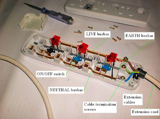
Have you ever wondered how it looks inside the extension unit of electrical power socket? The following few pictures can help you appreciate what is going on inside this piece of common household items.
Picture 1 –
The inside view of the electrical socket extension unit
=================
RELATED ARTICLES:
Lighting flexible conduits |
Weatherproof 13A switched sockets |
Metal-clad socket outlets |
A simple electrical installation |
1- Phase ELCB connection pictures |
Bare fluorescent light pictures |
Recessed down lights installation |
Bollard light pictures |
Light switch installation pictures |
Home wiring pictures |
Electric Meters |
Electrical Grounding Electrode Pictures |
Most Basic Principles of House Wiring |
MATV antenna bracket pictures |
Temporary socket outlet pictures |
Electrical installation pictures
=================
I think most readers can understand this picture clearly with the labels that I added.
For the absolute beginners that need explanations on what does what in this picture, let me just give brief descriptions.
Extension cord
I guess everyone knows this part. The extension cable has a three-pin plug at the other end of it. It is the plug that you insert into the wall socket.
Look at Picture 7 below to see the complete set of the extension socket and plug.
Extension cables
The extension cable that you see actually has three insulated cables inside it: the LIVE cable, the NEUTRAL cable and the EARTH cable.
Each of the three cables has their own color-coded insulation: Brown for LIVE; Blue for NEUTRAL and Green with yellow stripes for EARTH.
When you work on the connections of these cables, you have to make sure not to connect them in a wrong way.
If you connect in a wrong way, the electrical appliance that takes power from this extension sockets may still work.
For example, you mistakenly swap the connections of the blue and the brown cables.
However, the ON/OFF switch (the red colored piece in Picture 1) is located at the LIVE connection. Therefore, there is still a voltage going to the appliance connected to the socket.
Cable termination screws
There are 3 cables coming from the extension cord. So you have three connection points and therefore 3 connection screws.
The connection screw may seem simple enough, but not using it properly has been the cause of many house fires all over the world. See Picture 2 below for a closer view.
Picture 2 –
Cable termination screws

This is one of the biggest problems with house electrical wiring: the electrical parts look simple enough that everybody thinks they can handle it.
Yes, it is easy. But you must know enough about how the electrical components works to be able to handle it SAFELY.
If you do your own wiring, and you happen to replace an extension cord like one in the picture, make sure the connection of the copper conductor to the termination screw is strong and tight.
If the connection is not tight, then connection surfaces between the copper conductor and the screw present a high resistance to the current flow when the electrical appliance is turned on.
This high resistance will cause a high-energy loss at the connection, which is dissipated in the form of heat.
Over time, if the appliance is in operation long enough, the extension socket unit may overheat and become a source of fire.
A combustible material nearby such as a window curtain, old newspapers, even carpets and rugs may catch fire.
That is how a house electrical fire can get started. It is one of the most common cause also.
LIVE and NEUTRAL busbars
Picture 3 below gives a better view of the three busbars.
Picture 3 –
Busbar connections

As the cables are connected to the termination screws from the right side, the busbars are connected from the right side.
I know there are readers who are not very familiar with the word “busbar”. So let me just spend a few words on this part.
The purpose of a busbar is similar to electrical cables, which is to carry electric current.
In cables, we normally put insulation over the current carrying conductor. The reason to prevent touching of the conductor with other things and parts nearby.
However, at some places, there is already a very good place allocated to install the current carrying conductor. So the insulation may not be necessary.
The copper conductors inside the cables are flexible. This way it is easier to handle and bend around things.
However, making things flexible from metal materials cost money.
If at certain locations, the flexibility of the copper conductor is not necessary, then why waste money by using the flexible type, right?
Another advantage of using a solid conductor like busbar is that it is easier to make connection to it. In this case, multiple connections need to be made depending on how many socket points are needed.
I think the above description is enough to show what a busbar is.
It is “solid”, so it is a “bar”.
“Bus”? I am not that sure myself exactly why the this word is used here.
All the while, I only guessed that this word is used because in the old days, a “bus” is used to denote a main path, or a main road. That is where you could wait for a transport to go long distance.
You can also get the bus by waiting anywhere along the main road. My guess is that the public did not need to wait at the bus station or the “bus stop”.
That was the “bus transport”. This is the “bus bar”.
You can get power anywhere along the conductor part. There is no need to cut anything, or go to a terminal screw.
I am only guessing here. Your own guess is just as good as mine.
Now let’s go to the next component.
ON/OFF switch
Everybody knows what an ON/OFF switch is. It is exactly what the name says.
But there is one more component related to this on-off switch. It is called the pilot light.
Picture 4 –
The pilot light

In picture above, the pilot light is labeled. When the on-off switch of a particular socket unit is switched on, this light turns on.
Trivial as it seems, this feature has a very important safety purpose on an electrical socket.
When the light is on, you know there is power going into your electrical appliance. Even when the appliance is not operating (maybe because the appliance built-in on-off swith has been turned off, or the equipment has a blown fuse), you know the power is there.
It is therefore still dangerous.
The pilot light helps train our habits about safety.
When it is ON, there is DANGER for sure. There is no way we can pretend the switch on the socket is OFF.
The pilot lamp is connected in parallel with the appliance (to be connected). So even when the appliance power cord is broken, the pilot lamp lights up when the socket switch is ON.
The earth connection piece
Please observe in Picture 4 above the connection pieces from all three busbars in side the pin sockets.
Notice that while inside the “LIVE pin socket” and the “NEUTRAL pin socket” the connection to the plugs pins are made using a separate piece, the connection piece inside the “EARTH pin socket” is NOT A SEPARATE PIECE.
Why?
Because it is EXTREMELY IMPORTANT that the grounding connection from the appliance to the electrical grounding system MUST NEVER FAIL.
Therefore, the connection piece for the earth pin is part of the earth busbar.
Both is made from one solid piece of conductor and then bent around to form the earth busbar and the earth contacts (three sets of earth contacts actually, because there are three socket outlets in this socket extension unit).
Picture 5 below shows how the plug pins are inserted into the sockets.
Picture 5 –
13A sockets and a plug

Picture 6 and 7 below just show the whole assembly for readers who need them.
Picture 6 –
The cover for the cable termination compartment removed

Picture 7 –
The whole 13A socket extension assembly

I will see you again in the next post.
Copyright http://electricalinstallationwiringpicture.blogspot.com Electrical socket extension unit


