Showing posts with label HV switchboard. Show all posts

Tuesday, July 19, 2011

Cable ladder pictures

Below are a few pictures of one of the most important components of a building’s cable support system: cable ladders.
Picture 1 – Cable ladders at Consumer’s High Voltage Switchgears

=================
RELATED ARTICLES: Underfloor trunking below structural rebars |  MATV trunking riser |    Substation rooms layout diagram |  Conduit to trunking connectionsElectrical conduits and trunking picturesElectrical panel under water pipes  | Electrical busduct installation pictures | Electric conduit installation pictures  | Electric trunking installation pictures  | Electric Panel Installation Pictures  | FR electric cable installation pictures  | Multi storey building electric closets  | Underfloor trunking pictures  | Site-fabricated electrical trunking  | Electrical Services Color Codes  | Light switch installation pictures | Building’s electrical rooms layout | Electrical installation pictures
=================

These pictures were taken inside the Consumer HV Room of a new office building.

Picture 1 above shows the cable ladder connecting to the consumer HV switchgear panels.

Observe that there are four switchgear panels there.

On the cable ladders, there are only three HV cables. Is one of the HV switchgear panels kept as a spare?

Nope. Actually the supply authority’s HV Room is just next door to the consumer HV Room. The multi-core 11kV cable feeding supply to the consumer HV switchgears is run inside a cable trench connecting the two HV rooms. So it is not visible here.

To beginners in electrical installation works, observe carefully how the cable ladders are hung from the concrete slab using steel hanger rods. Observe also how close the spacing between adjacent hanger rods.

HV cables are heavy. The weight of the cables is one thing. There are also the bending forces of the cable when they are routed and bent along the cable ladders. At certain positions along the cable routes, the opposing bending forces of the cable ladders add to the weight of the cable itself.

What you can see in Picture 1 above are only very few cables. On many occasions in you career, you will see situations where cable ladders of the size shown in the picture sag. The forces and weight from the power cables can be that strong.

Picture 2 – Close up view of an angle iron support and the hanger rods


Observe how the angle iron support is supported at each end by a hanger rod.

Picture 3 – The cable ladder connecting HV switchgears to a transformer


Here the worker standing behind the transformer enclosure is doing the termination works of the 630 mm.sq. low voltage copper cables.

Recall that here we have four HV switchgear panels. One for the incoming cable from the supply authority switchgears in the room next door. The other three are the feeder cables for the consumers’ transformers.

In many designs, a consumer substation is designed to have separate rooms for HV switchgears and transformers. Here it has been designed to share the same room.

It does not really make much difference whether the rooms for both are shared or separate. The only real difference is the total space taken.

If separate rooms are used, it would take more space. In some installations, the space is expensive. Commercial buildings at prime areas of a big city are a classic example. Private owners count every dollar they spent on every functional space of the building. Many consider space taken by mechanical and electrical plants as a waste. So often design engineers end up with very little space to install their machines and equipment.

Here it is not so bad because it is a government office building.

The cable ladder shown in Picture 3 above provide a cable support for the HV cables from HV switchgear to a 1600 kVA transformer. This transformer serves the chiller plant behind the HV room.

The low voltage cables being terminated by the worker are also run on a cable ladder to go to the chiller plant LV switchboard.

Picture 4 – Cable ladder to 1000kVA transformers


This picture show the cable ladders to the other transformers in this substation.

Here you can see low voltage cables more clearly.

The transformers are 1000 kVA ones. While the 1600kVA transformer is dedicated to serve only the chiller plant (the main plant of the building’s centralized air-conditioning system), all other building electrical and mechanical loads including external loads (street lighting, carpark lighting, etc) are served by these two 11kV/415V transformers.

Observe how the low voltage cables coming out of the transformers are run of separate cable ladders to go to the main distribution switchboards in the LV Room at the other side of the wall.

Wall openings on the wall would later be sealed by an approved fire seal to prevent spreading of fire from one electrical room to the next.

Notice also the automatic fire suppression units (the red-painted round cylindrical objects mounted on the walls) installed at locations around the switchgear room. I will talk on the automatic fire suppression system in another post.
Copyright http://electricalinstallationwiringpicture.blogspot.com Cable ladder pictures

Thursday, March 18, 2010

Substation main earth bar pictures

You will find below a few pictures of HV electrical substation’s main earth bar. I took these pictures inside a Consumer HV room at one of my recent building projects.

Picture 1 – Location of the main earthing bar inside a HV Switchgear Room


Observe the location and position of the main earth bar in the HV room. At every electrical room of significant size, at least one main earth bar like this should be provided.

Picture 2 below shows a closer view of this earth bar.

=================
RELATED ARTICLES:
Exothermic welding: Cable to cable connectionsElectrical grounding  | Electrical Grounding Electrode Pictures  | Switchboard earthing picturesLightning roof conductor installationLightning Earth Rods Installation | Temporary Electrical Earthing Pictures | Electrical installation pictures
=================

Picture 2 – HV Room’s main earth bar


The purpose of having the main bar is simple.

All earthing conductors inside the HV room would be connected to this bar. That is the reason you can see in Picture 2 a number of ready-made termination holes complete with bolts, nuts and spring washers.

Notice the main copper earthing tape mounted along the substation wall in Picture 1. This is the main equipotential earthing conductor for this electrical room.

It should run through all perimeter walls of the room at a height of approximately 12 inch from the substation’s finish floor level. That is why you can see that in Picture 2 the left-most and right-most terminals have been connected with a horizontal copper tape conductor.

An ideal installation would have the main equipotential conductor run in a ring around the perimeter walls and both conductor ends connects to the main earth bar at the left-most and right-most terminals.

However, in this case it was not in a ring at the time this picture was taken because there was an entrance door at the wall in front of the 11 KV switchgear. Picture 1 was taken at the rear.

Later the horizontal copper tapes were connected into a ring by running additional conductor above the entrance door.

What are the conductors connected to the main earth bar in Picture 2?

The horizontal tapes at the left and right are what I have explained above.

The other three conductors have been installed vertically down into the cable trench.

(NOTE: Notice that the cable trench has been filled with river sand. Many installations prefer to have cable trenches filled with sand to avoid problems with rates and snakes playing hide and seek inside the cable trench.

Once a while these live beings find their way into the electrical switchgears and cause many problems including short circuits and intermittent trippings.

I have come across many operational problems because of these reasons.

To overcome these problems, many operation engineers prefer to just have all substation cable trenches filled with river sand. Then the trench is finished with approximately one inch of lean concrete on top of the sand and level with the substation floor.

When they need to do some work in the trench, they just knock down and break the thin concrete and dig out the sand.

No doubt this is a messy way of doing things, but it seemed to have been a very practical solution to these sorts of problems.)

Back to the earth tapes run vertical down into the cable trench. Where are these tape conductors for?

From the right, the first vertical conductor is connected to the HV switchgear equipotential conductors.

The center vertical conductor is connected to the earth busbar inside the switchgear compartments.

The last vertical conductor, at the far left, is the connection to the earthing electrodes outside the HV room.

Picture 3 – Disconnecting earth terminals


Some of the readers may not notice that the earth bar in Picture 2 is actually a two-piece bar. The two separate pieces are much more visible in Picture 3 above.

Notice that there is just one terminal (other than the terminal for connecting the two bars) on the short piece, while there are six terminals on the longer bar.

This has been designed to be so. The terminal on the short bar is called “disconnecting terminal”. The whole assembly is purchased readily assembled by manufacturer.

Usually earth bar with one or two disconnecting terminals are readily available. If an electrical contractor needs more disconnecting terminals, then it need to be ordered and it would be fabricated as required by the project at hand.

The terminals on the shorter piece are intended for testing and trouble-shooting purposes. That is why the conductor to the grounding electrodes is often connected to the short piece.

However, so clients forbid the use of the disconnecting terminals altogether. These sorts of clients usually manage many separate electrical installations with separate local operation teams.

It is usually not always easy to ensure an adequate level of competency of each member of the local operation and maintenance teams.

An earth lead conductor connected to the disconnecting terminal may easily lead to a total absence of connection to the earth electrode.

This presents a very serious safety risk.

This lead to a policy of forbidding the use of the disconnecting terminals. Therefore, all their substations would have single-piece earth bars.

Picture 4 – HV switchgear body earth conductor


This photo gives a clearer view of the switchgear equipotential bonding conductor.

As you may be aware, the switchgear came in separate smaller panels and the individual panels are then connected and bolted together at site.

The switchgear body earth (another name for the enclosure equipotential bonding) conductors, as indicated in Picture 4, have also been installed and bolted to each individual panel.

Therefore, these individual lengths of body earth conductors are connected and bolted to each other at the construction site.

The short inter-connecting copper pieces and all accessories including bolt-and-nuts for making the complete connection are provided by the switchgear manufacturer and shipped together with the rest of the panels.

Picture 5 – Bolt, nut and spring washer


This may be obvious for most readers, but some beginners may be silently screaming for help. So I labeled these components for them since they are such critical components in the electrical grounding system.

Picture 6 – Earth bar insulator post


Copyright http://electricalinstallationwiringpicture.blogspot.com Substation main earth bar pictures

Friday, February 12, 2010

Switchboard earthing pictures

This post provides a few pictures of switchboard earthing. They are pictures of actual switchboards and electrical DB’s that were installed in one of the projects I was involved in.


Picture 1 – LV sub-switchboard


=================
RELATED ARTICLES:
Exothermic welding: Cable to cable connections | Electrical grounding  | Substation main earth bar picturesElectrical Grounding Electrode Pictures   | Lightning roof conductor installationLightning Earth Rods Installation | Temporary Electrical Earthing Pictures | Electrical installation pictures

=================

Picture 2 – Three-pole 160 A Terasaki MCCB and the neutral link


Picture 1 above shows a sub-switchboard at one of the upper floor of the multi-storey building.

Picture 2 shows the main isolation switch at the switchboard. I show the enlarged version of this component because I want to show the readers the neutral link component on the right of the MCCB. The neutral link is a very important part of the safety aspects of an electrical installation. I may want to refer to component later in this post or maybe when I send an update.

In Picture 1, you can see at the bottom left corner of the sub-switchboard the earthing connection to earth the switchboard front door. Picture 3 below gives an enlarged view.

Picture 3 – Earthing conductor to earth the sub-switchboard front door


Observe that the conductor is made of braided aluminium conductor. The braided type of conductor is a very good material for earthing door switchboards because the door is a frequently moved part of the board.

If an unsuitable material is used, the frequent movement of the door will either weaken and damage the conductor, or loosen the contacts at the door and the main panel cubicle. A loosened contact would increase the contact electrical resistance and defeats the purpose of having a properly sized earth conductor in the first place.

A loosened earth conductor is usually seldom noticed during the operation of the equipment until something happens. The problem is that “something” may actually be a serious electrical shock.

It is for this reason the earthing of these grounding connections should be properly checked by visual inspection during the installation works.

Notice also the termination to the switchboard door. The braided aluminium conductor is terminated using a compression type cable termination lug. It is fixed to the door using appropriately sized earthing bolt and nut with spring washers.

Picture 4 – Lighting and small power distribution board (DB)


Picture 4 above shows a floor distribution board for the lighting final circuits and also for the small power needs at the floor level.

Both the sub-switchboard in Picture 1 and this DB were not actually installed yet at the time I took these pictures. They were still on the floor at the storage area of the construction site. That is why you see these pictures were taken at angles looking downward to the boards.

The earthing connection to the front door of the board was also using the braided aluminium similar to Picture 1, as shown in the enlarged view below.

Picture 5 – DB door earthing conductor


There also is another type of panel door earthing conductor in common practice, as you can see in Picture 6 and Picture 7 below.

Picture 6 – Another electrical DB


Picture 7 – DB door earthing using green insulated PVC cable


Here the conductor is just the normal PVC insulated wiring cable with green colored insulation. The PVC cable is not very flexible. It is therefore is installed in the inverted U-shape as in Picture 7.

Sometimes the PVC cable is formed into coils between the two mounting bolts to give similar flexibility. I do not have the picture of this method now, but I will send an update as soon as I can get one.

I personally prefer the braided aluminium conductor as in Picture 1. However, contractors would normally prefer the PVC cable type because it is simply cheaper.

Manufactures would always prefer the Picture 1 method because it make the their board looks more high-quality. However, they would have to follow contractor’s choice unless the design consultant specifically stated their requirements clearly in the contract specifications.

Main Earthing Cable

In all the above Pictures, I have only highlighted the internal branch earth connections. I wish to highlight the main earthing conductors of the switchboards.

Look at the bottom of the distribution board in Picture 6. You can see at the bottom of the DB cubicle a length of green PVC insulated wire just laid there and stops just below the three-pole MCB at the bottom right corner of the DB. You can see it better in the enlarged view (Picture 8) below.

Picture 8 – Distribution board main cables


Unlike the first two electrical panels, this distribution board has already been wall-mounted in its final position. However, it is not yet wired and the cables not terminated. The electrical contractor just wanted to get my approval of the DB mounting method before they proceed with the cable termination works.

You can see the sub-main supply cables coming down from the top trunking. The outer sheath and wire armor of the 4-core armored PVC cables have been terminated with a cable gland. That is why you can see the individual cable cores coming down along the right side of the cubicle wall.

An extra slack has been provided during the sub-main cable installation to ensure there is enough length provided in case adjustment need to be made to the final position of the DB. The actual route inside the DB also may require some extra slack to the incoming cable cores.

Back to the earthing cable. The specifications for this project requires the use of 3 mm by 75 mm copper tapes as the earthing conductors for all submain circuit.

However due to installation difficulties I have allowed the use of PVC copper cables as an alternative to earth the sub-switchboards and distribution boards on case by case basis. This DB is one of the cases.

Therefore, here the main earth conductor is the PVC cable. This cable is connected to the main earthing conductor, which is the 3 mm x 75 mm copper tape, at the multi-storey building’s riser room.

You can see in Picture 8 that the earthing cable is not terminated yet. It is a common practice to provide a main earthing busbar in side an electrical board. The earthing busbar is usually pre-installed at the factory just like the rest of the components.

I do not see the earth busbar in the picture. When I went for the inspection and took these pictures, I was only paying attention to the mounting of the board. I only realized the missing earth busbar when I started to write this article. In any case, this matter would be picked up during the inspection of the internal wiring of the distribution board.

If the main earth busbar is actually missing, the electrical contractor will need to install the busbar himself at a suitable location inside the DB. The green PVC cable will then be terminated to the busbar using compression type cable lug.

The fixing to the busbar will also be similar to the door earthing method explained above: bolt and nut with spring washer.

Usually the busbar would be pre-drilled with sufficient number of termination points plus a few spare points. This will eliminate the need for disassembly of the busbar and all existing connections when additional earthing connections are needed during the life of the switchboard.

There is one more picture that I would like you to see on the earthing of LV electrical panels. See Picture 9 below.

Picture 9 – Switchboard earthing conductor


Where is the switchboard??

They have not been installed yet at the time I took this picture. These “dropper trunkings” have been installed but they stop just a few feet above the location of the distribution board and switchboard.

Observe the two lengths 3 x 75mm copper tape coming down from the electro-galvanized steel trunking. This is the standard earthing conductor used for this project. The PVC cables used in Picture xx was a replacement to this copper tape.

Earthing of 11 kV switchboards

The switchboards and the distribution boards shown in all the above pictures are low voltage boards. They are rated 240V/415V at 50 Hz supply.

Now I will show you a few pictures of high voltage (HV) switchboards. These boards are designed for 11 kV incoming supply.

Picture 10 – 11 kV switchboard rear view


Picture 11 – Closer view of the earthing copper conductor


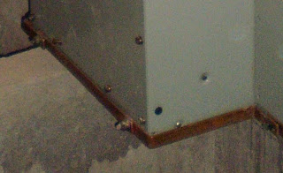
Why do I show the rear view of these HV panels?

Because these panels are floor mounted with rear access. The LV panels above have been designed for mall-mounted installation. Therefore, they do not have rear access.

Observe the long strip in brown color at the lower edge of the switchboard. This is the earthing copper conductor for the high voltage switchgear panels.

Note: Some readers may notice that I use the terms “board” and “panel” interchangeably. For LV small electrical panels the two terms do not really have any significant difference.

However, for large LV switchboards and high voltage switchboards, the two terms cannot be interchangeable. Look at Picture 12 below.

Picture 12 – HV panel


This is one HV panel. The other big object at the left of the panels is actually another HV panel, which is still inside its waterproofed wrapping.

A high voltage switchboard consists of one or more of these panels. In other words, the panel is a section of the switchboard.

Notice the brown strip at the bottom edge of the panel in Picture 11. This is the earthing copper conductor that you see in Picture 10.

From this picture it is obvious that the long copper strip in Picture 10 is actually jointed lengths of short individual copper strip that are part of the individual HV panels.

This short copper strip at each panel has actually been installed at the manufacturer’s factory. Short lengths of the conductors are then provided complete with pre-made jointing holes and shipped together with the rest of the panels.

The electrical contractor then only needs to re-assemble all the pieces together into a complete HV switchboard.

Picture 13 – Another view of the earthing conductor


This photograph also shows the HV cables installed in the cable trench. The one going into the end panel is the feeder cable to one of the local transformers. While the other one is the incoming supply cable from the authority HV switchroom just adjacent to this HV switchroom.

Picture 14 – Substation earthing


Picture 14 shows the substation main earthing conductors. All substation should be installed with these copper tape conductor along the walls of the substation. It is usually called the substation main earthing conductors. These conductors are terminated to a main earthing busbar.

In this case, the earth busbar has not been installed yet. However the location is as indicated by my comment on the picture.

The main conductor running horizontally on the walls will be cut at the location shown. The busbar will be installed there. The cut horizontal conductors (now it has become 2 lengths after the cutting) plus the three vertically mounted conductors already there will be terminated to the earth busbar using properly sized bolts, nut and spring washers.

Note: You can also see more pictures of electrical wiring by visiting this post, Pictures of electrical wiring.


Copyright http://electricalinstallationwiringpicture.blogspot.com Switchboard earthing pictures