Showing posts with label Earthing cables. Show all posts

Friday, May 17, 2013

Exothermic welding: Cable to cable connections

Just a few pictures today … on exothermic welding joint of earthing copper cables.

Picture 1: Cable-and-mould set-up for a cable-to-cable exothermic joint
(Click on the picture to enlarge it.)

=================
RELATED ARTICLES:
Electrical Grounding Electrode Pictures | Electrical grounding  | Substation main earth bar pictures  | Switchboard earthing pictures | Lightning Earth Rods Installation | Temporary Electrical Earthing Pictures | A simple electrical installation |  Electrical installation pictures

=================

The above picture shows the set up for a cable to cable connection.
For the uninitiated, I have labeled the components in Picture 01 and show them again in Picture 02 below.

Picture 02: Exothermic welding process set-up labeled
(Click on the picture to enlarge it.)

I will not write much today and I have serious doubt that I will be able to write long posts again in the near future.

The best I can do is to show you some pictures. When I have more time I will write longer.

Note that the part that I labeled “explosive powder” is not really explosive powder. Well, It IS explosive, but it is not an EXPLOSIVE.

It is actually some powdered mixture of copper oxide and aluminium. When ignited, the mixture produces a very high temperature reaction that molten the copper and aluminium components which then flow into whatever cavities between the conductors to be joined, as well as form a thick layer of alloy envelope around them.

This you can see in Picture 07 below.

Picture 03: Just a closer view of the mould.
(Click on the picture to enlarge it.)

Picture 04: A shot during the combustion
(Click on the picture to enlarge it.)

Picture 05: A cable-to-cable joint still red-hot
(Click on the picture to enlarge it.)

For the curious, the earthing cable conductors in the pictures are 95 mm.sq stranded copper cables.
This installation was part of an earth mat type earthing system. High voltage substations for voltages 33kV and above usually have some sort of “step voltage” protection and the earth mat or earth grid is part of the “step voltage protection system”.

For beginners who have no idea at all of what all this means, have no worry. I will send a post or two on “earth mat” and “step voltage“ soon.

Picture 06: A completed cable-to-cable joint
(Click on the picture to enlarge it.)

Picture 07: A closer view of the finished exothermin joint.
(Click on the picture to enlarge it.)

Okay, folks. See you in the next post.

Jimmy Lee Wan Seng
(Information Trader)

Copyright http://electricalinstallationwiringpicture.blogspot.com Exothermic welding: Cable to cable connections

Thursday, March 4, 2010

Lightning Earth Rods Installation

The installation of a lightning earth rod is similar to an electrical grounding electrode. In fact, both are exactly the same thing. There is one small difference though. A lightning earthing need only achieve 10 ohms of maximum resistance, while an electrical grounding may need less than 1 ohms. That is ten times lower resistance, which may mean ten times the number of electrodes that need to be installed.


Diagram 1 – The overall diagram of a lightning protection system


=================
RELATED ARTICLES:
Exothermic welding: Cable to cable connections | Electrical grounding  | Substation main earth bar picturesElectrical Grounding Electrode Pictures  | Switchboard earthing picturesLightning roof conductor installation  | Temporary Electrical Earthing Pictures | Electrical installation pictures

=================

Diagram 2 – A closer view showing the grounding rod chamber and the lightning test point on the wall of the building


Diagram 3 – Cross section diagram of the earthing rod installation


Picture 4 – An existing ground rod chamber


If you have read the other post, Electrical grounding electrode pictures, you will see that this chamber looks the same as the electrical grounding electrode. They are the same materials and construction.

Only the required maximum resistance values are different.

Picture 5 – A grounding rod installation in progress. The earthing chamber is not installed yet


This lightning rod has been connected as a temporary measure. Later a proper and more permanent connection would be done with the chamber installed to protect the electrode connection.

Picture 6 – The earth chamber for the earth rod in Picture 5


This chamber is bigger than the chamber in Picture 4. The sizes of grounding rod chambers vary between 10 in x 10 in to 13 in by 13 in. As far as I know there is no real technical reason for the difference other than that bigger chambers would give more room for the servicing and maintenance work during the life of the installation.

Why should you care about lightning rods?

This is my first post on the subject of lightning protection in this blog. Therefore, I am trying to make it light so that beginners have no trouble digesting the materials.

Another reason for making it easily digestible to casual readers is because every year many people die of lightning strikes whether indirectly or by direct strikes.

I know of a few cases already in my area where a few people died inside their house when the lightning hit the houses.

The worst of these types of incidents that I know was about 4 years ago where all members of a family of four died from a single strike to their house at night.

The point I am trying to make here is that the issue of lightning protection relevant to everyone, not just the lightning specialist or the electrical engineers.

Everyone should be concerned about the dangers of lightning just like the dangers or road accidents.

What Is Lightning?

The lightning strikes come from the clouds that have been charged with static electricity to a very high voltage (i.e. electrical pressure).

These clouds get charged due to the movements and frictions among themselves up in the sky. The electric currents do not flow from the clouds until the air separating them breaks down, that is when it can no longer handle the high voltage difference between a cloud and the earth surface, or between the clouds themselves.


How Is It Created?

When the air breaks down, electric current flows through the air from the cloud to earth and currents in the magnitude of tens of thousands of amperes for each strike are daily occurrences in some parts of the world.

In fact a strike can carry over 200,000 amperes of electric current.

Just consider an electrical overload or a short-circuit in our house wiring. These electrical faults would usually result in the current of only a few hundred amperes. Yet, they can already start fires and cause a lot of damage to properties.

Compare this to the 200, 000 amperes that can be carried by each of the lightning strikes, then we can imagine what kind of damage a lightning strike can do.

Even multiple human casualties are common results from a single lightning strike to an occupied house.

Is your Home Safe From Lightning Strikes?

The question now: Is your home, office or shop building adequately protected against these highly possible attacks from the sky?

Buildings of significant sizes usually have a proper lightning protection system installed. This sort of buildings normally has a knowledgeable management to look after their maintenance.

However, for houses or very small buildings, they may not have the people knowledgeable enough to ensure that adequate protection has been installed and maintained in a satisfactory condition.

How Lightning Protection Works

The conventional design of a lightning protection system is actually an electrical cage. The electrical cage is constructed of electrical conductors or cables interconnected in a network over the roof and the sides of a building.

A few vertical air finials approximately one foot high are normally visible above the roof, and these are connected to and become part of the roof conductor network.

When a lightning bolt strikes, it usually (even though not all the time) strikes these roof electrical conductors. The electrical current will be routed to the ground through a number of down conductors installed uniformly around the perimeter walls of the building or the house at approximately 20 meter spacing.

Once the electrical charge is routed into the ground, the charge must be dissipated into the mass of earth quickly enough.

If not, a high voltage will be developed at ground level and this can damage equipment cause injuries or even death to the building occupants.

The quick dissipation of the electrical charge into the earth mass is accomplished by the installation of steel rods of approximately half-inch in diameter to the depth of a few feet into the ground.

On the ground surface, the top of this steel rods are usually enclosed inside a small square concrete inspection chambers called the earth chambers.

The lightning earthing rods

Seen from the perspective of a building structure, a lightning protection system generally consists of three sections: the aerial conductor network, the down conductors, and the earthing part or what is usually called the lightning rods.

By design, the function of the aerial conductor network is to present at the highest point of the structure an area that will attract lightning strikes away from other parts of the building.

The electrical current carried by the strikes will then be routed down through the down conductors to the lightning rods at the ground level or the lowest level in multiple basement structures.

The purpose of lightning rods

The purpose of the lightning rods is to help dissipate the discharge of the electrical energy carried by up to 200 kilo-ampere of electrical current into the earth mass as quickly as possible.

This is very critical to the performance of the whole system, because a lower rate of energy dissipation will expose a higher risk of injuries or fatalities to human lives (or livestock) due to the presence of a higher voltage gradient on the ground.

Besides, with a slower rate of dissipation there is a higher risk of damage to properties due to flashovers from the lightning down conductors to any ungrounded metal parts nearby.

It is also essential that the down conductors be routed along the most direct path to the ground. Therefore the location of the rods should be beneath the building or as near as possible to the building structure.

Location of the grounding rods

Quite often designers locate the rods at some distance away from the building. This is unnecessary and it may in fact increase the risk of electrocution due to the presence of the voltage gradient across a wider area of the ground.

The Materials

The lightning rods are usually steel reinforced copper rods approximately half an inch in diameter, and driven deep into the ground. In an area free of rocks, they can easily be driven 18 feet or more into the ground.

The Installation Methods

This method of lightning rod installation can give a good reading because the rod surface easily makes an effective contact to the earth mass. Deep driving like this also gives good reading because as the rod is driven into the lower level of soil, it comes into the water level that is not affected by seasonal conditions.

Other Installation Methods

Other methods are also used instead of the deep driven steel rods to provide the best possible contact with the earth mass. The choice depends on the prevailing ground conditions: the soils resistivity and the soil moisture content.

Urban Areas

In urban areas, a few earth rods are usually installed first and looped below ground using copper conductors. Their combined resistance with all rods in parallel is measured and it must not exceed 10 ohms as required by the international standard.

If the combined resistance is above 10 ohms, more rods are driven and connected until the 10-ohm requirement is met.

Isolated Areas

However, in locations away from recent developments, the soil conditions may not be known without actual measurements. Therefore, the soil resistivity tests must be carried out to determine the earthing method most suitable and the extent of the work required.

At times when the soil is sitting on rocky subsoil below ground, a hole may have to be drilled deep down. A depth 100 m or more is not uncommon in more serious cases.

In these situations, a long copper rod is inserted deep into the hole to get the 10-ohm requirement.

In more extreme cases, even this is not enough and soil conditioning agents like Bentonite or conductive cement need to be used.

These compounds are prepared as a slurry or mix, and poured down the vertically drilled hole, creating a lower resistance between the embedded copper earth electrode and the surrounding soil.

The cases that require this method of lightning rods installation may not be very common. However, it does happen.

An example may be a district gas pressure reduction stations, or other similar type of plants.

Combine all the grounds

Finally, it should be remembered that a combined earth with other services can much reduce the overall cost of the grounding for these separate systems.

This is also necessary to prevent side flashovers from the lightning conductors.

In the end it may well be that the lightning rod network is the shared earthing system for all services.

Check out the following posts for more pictures on grounding rods and other issues:

Electrical installation pictures;
Temporary electrical earthing pictures.


Copyright http://electricalinstallationwiringpicture.blogspot.com Lightning Earth Rods Installation

Sunday, February 21, 2010

Electrical Grounding Electrode Pictures

The following pictures show examples of grounding electrodes and earthing chambers for electrical earthing systems.

Picture 1 – Earthing chambers


=== RELATED ARTICLES:  Exothermic welding: Cable to cable connections | Electrical grounding  | Substation main earth bar pictures  | Switchboard earthing picturesLightning roof conductor installationLightning Earth Rods Installation | Temporary Electrical Earthing Pictures | A simple electrical installation | Electrical socket extension unit  | 1- Phase ELCB connection pictures  | Bare fluorescent light pictures  | Recessed down lights installation  | Bollard light pictures  | Light switch installation pictures  | Home wiring pictures  | Electric Meters  | Most Basic Principles of House Wiring | MATV antenna bracket pictures | Electrical installation pictures |   Temporary electrical installation pictures |  Temporary lighting installation pictures

=================

Grounding electrodes are driven several feet into the ground soil using a hammer or powered rod driver tools.

The connection is made at the top of each electrode to the earthing conductor coming from the electrical equipment to be grounded, or the down conductor of the lightning protection system.

This connection must be protected and it should be available for inspection and servicing in the future. It is therefore enclosed inside a chamber that is provided with a removable cover so that the grounding connection is easily accessible.

Picture 1 above is an example of the earthing chambers. This one is one of the smaller-sized types, approximately 8 inch by 8 inch of internal clearance inside the square chamber. Some designs are bigger.

Picture 2 below shows the same grounding chamber with the cover removed. Notice the strong metal pull eye provided to help removal of the cover. The earth chamber is installed in the ground and over time the gaps between the cover and the chamber are eventually filled with dirt, sand and soils. This makes the opening of the cover very difficult sometimes.

Picture 2 – The earthing chamber with the cover removed


What you can see inside the chamber in Picture 2 is the earthing copper tape that has been bonded to the grounding electrode. Picture 3 shows the bonding this better.

Picture 3 – Another view of the grounding chamber


Picture 4 – Closer view of the grounding rod


I have attached a diagram (see Diagram 5 below) that gives an overall picture of the installation of the electrical grounding electrode.

Diagram 5 – Grounding electrode and earth chamber


From the diagram you can see how the earthing copper tape is installed below ground and enter the grounding chamber from below. Then the end of the copper tape is connected to the top of the electrode using a clamp.

However the copper tape connection to the earth rod in the above pictures does not use a clamp. That is why you cannot see any sign of a clamp in the picture.

The earthing connection in this case uses thermo-weld bonding. That is the reason you can see the copper see to connect to the vertical rod at ninety-degree angle. The thermo-weld joint can be done much easier in this formation.

Whether the choice is to use the compression clamp or the thermo-weld bonding is a matter of choice depending on the number of factors.

Properly done, the thermo-weld joint is virtually maintenance free. You would not even need the inspection chamber, even though it is better to have one because you may need to make more connections to the grounding rod in the future.

The joint made by the compression clamp, on the other hand, need to be inspected regularly at certain intervals to make sure there is no interference to the joints. The earthing resistance test also need to be tested every one or two year to ensure it is within the acceptable level.

A total earthing resistance that is too high will present a serious shock hazard to users of the electricity within the premise concerned.

The pictures below show joints of earthing conductors to grounding rods.

Picture 6 – Copper tape to earthing electrode connection


Some readers may ask where the earthing chamber in this picture is.

Actually the installation here has not yet been completed. I have allowed the contractor to proceed with the earthing installation so they can energize the power supply early.

The earthing chamber would be installed later after the roadwork is ready for the installation of the earthing chambers. This particular earth chamber was actually installed near the road curb of the internal road. Try to avoid this if you can.

Picture 7 below shows a broader view of the electrode


As you can see, the connection and part of the electrode seems too high above the ground. Actually that would be the real finished level of the internal road which was still under construction. That was the reason the earthing chamber was not installed yet.

Picture 8 – Earthing copper cable connection to earth rod


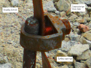
Picture 8 above shows another earthing connection inside the earth chamber using the compression type brass clamp.

Observe that the top end of the electrode in this picture does not have the screw thread that is clearly visible in the electrode of Picture 6.

That is because the real top end of the earth rod in Picture was much higher but it was cut to match the expected final ground level.

Copyright http://electricalinstallationwiringpicture.blogspot.com Electrical Grounding Electrode Pictures

Friday, February 12, 2010

Switchboard earthing pictures

This post provides a few pictures of switchboard earthing. They are pictures of actual switchboards and electrical DB’s that were installed in one of the projects I was involved in.


Picture 1 – LV sub-switchboard


=================
RELATED ARTICLES:
Exothermic welding: Cable to cable connections | Electrical grounding  | Substation main earth bar picturesElectrical Grounding Electrode Pictures   | Lightning roof conductor installationLightning Earth Rods Installation | Temporary Electrical Earthing Pictures | Electrical installation pictures

=================

Picture 2 – Three-pole 160 A Terasaki MCCB and the neutral link


Picture 1 above shows a sub-switchboard at one of the upper floor of the multi-storey building.

Picture 2 shows the main isolation switch at the switchboard. I show the enlarged version of this component because I want to show the readers the neutral link component on the right of the MCCB. The neutral link is a very important part of the safety aspects of an electrical installation. I may want to refer to component later in this post or maybe when I send an update.

In Picture 1, you can see at the bottom left corner of the sub-switchboard the earthing connection to earth the switchboard front door. Picture 3 below gives an enlarged view.

Picture 3 – Earthing conductor to earth the sub-switchboard front door


Observe that the conductor is made of braided aluminium conductor. The braided type of conductor is a very good material for earthing door switchboards because the door is a frequently moved part of the board.

If an unsuitable material is used, the frequent movement of the door will either weaken and damage the conductor, or loosen the contacts at the door and the main panel cubicle. A loosened contact would increase the contact electrical resistance and defeats the purpose of having a properly sized earth conductor in the first place.

A loosened earth conductor is usually seldom noticed during the operation of the equipment until something happens. The problem is that “something” may actually be a serious electrical shock.

It is for this reason the earthing of these grounding connections should be properly checked by visual inspection during the installation works.

Notice also the termination to the switchboard door. The braided aluminium conductor is terminated using a compression type cable termination lug. It is fixed to the door using appropriately sized earthing bolt and nut with spring washers.

Picture 4 – Lighting and small power distribution board (DB)


Picture 4 above shows a floor distribution board for the lighting final circuits and also for the small power needs at the floor level.

Both the sub-switchboard in Picture 1 and this DB were not actually installed yet at the time I took these pictures. They were still on the floor at the storage area of the construction site. That is why you see these pictures were taken at angles looking downward to the boards.

The earthing connection to the front door of the board was also using the braided aluminium similar to Picture 1, as shown in the enlarged view below.

Picture 5 – DB door earthing conductor


There also is another type of panel door earthing conductor in common practice, as you can see in Picture 6 and Picture 7 below.

Picture 6 – Another electrical DB


Picture 7 – DB door earthing using green insulated PVC cable


Here the conductor is just the normal PVC insulated wiring cable with green colored insulation. The PVC cable is not very flexible. It is therefore is installed in the inverted U-shape as in Picture 7.

Sometimes the PVC cable is formed into coils between the two mounting bolts to give similar flexibility. I do not have the picture of this method now, but I will send an update as soon as I can get one.

I personally prefer the braided aluminium conductor as in Picture 1. However, contractors would normally prefer the PVC cable type because it is simply cheaper.

Manufactures would always prefer the Picture 1 method because it make the their board looks more high-quality. However, they would have to follow contractor’s choice unless the design consultant specifically stated their requirements clearly in the contract specifications.

Main Earthing Cable

In all the above Pictures, I have only highlighted the internal branch earth connections. I wish to highlight the main earthing conductors of the switchboards.

Look at the bottom of the distribution board in Picture 6. You can see at the bottom of the DB cubicle a length of green PVC insulated wire just laid there and stops just below the three-pole MCB at the bottom right corner of the DB. You can see it better in the enlarged view (Picture 8) below.

Picture 8 – Distribution board main cables


Unlike the first two electrical panels, this distribution board has already been wall-mounted in its final position. However, it is not yet wired and the cables not terminated. The electrical contractor just wanted to get my approval of the DB mounting method before they proceed with the cable termination works.

You can see the sub-main supply cables coming down from the top trunking. The outer sheath and wire armor of the 4-core armored PVC cables have been terminated with a cable gland. That is why you can see the individual cable cores coming down along the right side of the cubicle wall.

An extra slack has been provided during the sub-main cable installation to ensure there is enough length provided in case adjustment need to be made to the final position of the DB. The actual route inside the DB also may require some extra slack to the incoming cable cores.

Back to the earthing cable. The specifications for this project requires the use of 3 mm by 75 mm copper tapes as the earthing conductors for all submain circuit.

However due to installation difficulties I have allowed the use of PVC copper cables as an alternative to earth the sub-switchboards and distribution boards on case by case basis. This DB is one of the cases.

Therefore, here the main earth conductor is the PVC cable. This cable is connected to the main earthing conductor, which is the 3 mm x 75 mm copper tape, at the multi-storey building’s riser room.

You can see in Picture 8 that the earthing cable is not terminated yet. It is a common practice to provide a main earthing busbar in side an electrical board. The earthing busbar is usually pre-installed at the factory just like the rest of the components.

I do not see the earth busbar in the picture. When I went for the inspection and took these pictures, I was only paying attention to the mounting of the board. I only realized the missing earth busbar when I started to write this article. In any case, this matter would be picked up during the inspection of the internal wiring of the distribution board.

If the main earth busbar is actually missing, the electrical contractor will need to install the busbar himself at a suitable location inside the DB. The green PVC cable will then be terminated to the busbar using compression type cable lug.

The fixing to the busbar will also be similar to the door earthing method explained above: bolt and nut with spring washer.

Usually the busbar would be pre-drilled with sufficient number of termination points plus a few spare points. This will eliminate the need for disassembly of the busbar and all existing connections when additional earthing connections are needed during the life of the switchboard.

There is one more picture that I would like you to see on the earthing of LV electrical panels. See Picture 9 below.

Picture 9 – Switchboard earthing conductor


Where is the switchboard??

They have not been installed yet at the time I took this picture. These “dropper trunkings” have been installed but they stop just a few feet above the location of the distribution board and switchboard.

Observe the two lengths 3 x 75mm copper tape coming down from the electro-galvanized steel trunking. This is the standard earthing conductor used for this project. The PVC cables used in Picture xx was a replacement to this copper tape.

Earthing of 11 kV switchboards

The switchboards and the distribution boards shown in all the above pictures are low voltage boards. They are rated 240V/415V at 50 Hz supply.

Now I will show you a few pictures of high voltage (HV) switchboards. These boards are designed for 11 kV incoming supply.

Picture 10 – 11 kV switchboard rear view


Picture 11 – Closer view of the earthing copper conductor


Why do I show the rear view of these HV panels?

Because these panels are floor mounted with rear access. The LV panels above have been designed for mall-mounted installation. Therefore, they do not have rear access.

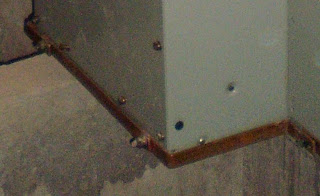
Observe the long strip in brown color at the lower edge of the switchboard. This is the earthing copper conductor for the high voltage switchgear panels.

Note: Some readers may notice that I use the terms “board” and “panel” interchangeably. For LV small electrical panels the two terms do not really have any significant difference.

However, for large LV switchboards and high voltage switchboards, the two terms cannot be interchangeable. Look at Picture 12 below.

Picture 12 – HV panel


This is one HV panel. The other big object at the left of the panels is actually another HV panel, which is still inside its waterproofed wrapping.

A high voltage switchboard consists of one or more of these panels. In other words, the panel is a section of the switchboard.

Notice the brown strip at the bottom edge of the panel in Picture 11. This is the earthing copper conductor that you see in Picture 10.

From this picture it is obvious that the long copper strip in Picture 10 is actually jointed lengths of short individual copper strip that are part of the individual HV panels.

This short copper strip at each panel has actually been installed at the manufacturer’s factory. Short lengths of the conductors are then provided complete with pre-made jointing holes and shipped together with the rest of the panels.

The electrical contractor then only needs to re-assemble all the pieces together into a complete HV switchboard.

Picture 13 – Another view of the earthing conductor


This photograph also shows the HV cables installed in the cable trench. The one going into the end panel is the feeder cable to one of the local transformers. While the other one is the incoming supply cable from the authority HV switchroom just adjacent to this HV switchroom.

Picture 14 – Substation earthing


Picture 14 shows the substation main earthing conductors. All substation should be installed with these copper tape conductor along the walls of the substation. It is usually called the substation main earthing conductors. These conductors are terminated to a main earthing busbar.

In this case, the earth busbar has not been installed yet. However the location is as indicated by my comment on the picture.

The main conductor running horizontally on the walls will be cut at the location shown. The busbar will be installed there. The cut horizontal conductors (now it has become 2 lengths after the cutting) plus the three vertically mounted conductors already there will be terminated to the earth busbar using properly sized bolts, nut and spring washers.

Note: You can also see more pictures of electrical wiring by visiting this post, Pictures of electrical wiring.


Copyright http://electricalinstallationwiringpicture.blogspot.com Switchboard earthing pictures