The following few pictures and diagrams show the connections of the 1-phase ELCB unit inside a house electrical panel. They are for readers who wish to understand how the electric shock protection devise is connected to their house electrical wiring.
The leakage current (or leakage voltage) usually occurs when there is a defect in a part of the installation, which can be caused by faulty components or by injuries to the insulation of the wiring, cables, electrical appliances or other accessories such as the switches and socket outlets.
When there is leaked current that exceeds the preset value of the ELCB setting, the ELCB then breaks the connection of the incoming electricity supply from the internal house wiring.
This is done automatically within a fraction of a second of the leakage being detected, before the magnitude of the leakage current reaches a level that can cause serious injuries or electrocution.
With a proper use of ELCB, the possibility of serious injuries due to electric shock to a person who accidentally come into contact with energized metal casing of an appliance is minimized.
B. ELCB circuit
An ELCB is not a simple component. Inside the casing of the ELCB unit you can see in Picture 2 above are a number of components. These components are assembled together and wired into a small electrical circuit with a dedicated purpose.
Diagram 3 below shows the internal circuit of a single phase ELCB. This type is one of the most commonly used type in house electrical panels.
However, before I go further, a few points need to be kept in mind throughout this article.
1. When it first came to be used, the ELCB was actually a voltage-operated device that was designed to detect a current leaking through the earth path of electrical equipment and appliances.
I hope you know the difference between electric current and voltage. If you are not sure, just read this post, Most Basic Principles of House Electricity. I am sure you will find out that house electricity is quite easy to understand.
2. The circuit that you see here is actually a residual current devise (RCD), or residual current circuit breaker (RCCB). This circuit is like a second generation of ELCB design.
It is based on the principle of magnetic core balance and the trigger core is current operated instead of voltage operated as in the original design of ELCB.
3. In terms of performance, the residual current circuit breaker is definitely better. The performance of the old ELCB did not have any problem, but the residual current device can do the same and more.
4. Even though the original ELCB design is no longer used, the name stuck.
Some textbooks now use the term RCD or RCCB to refer to this shock protection devise. However, in many situations the “ELCB” is more popular.
Therefore, the convention has not been changed. It is for this reason that throughout this blog I will keep on using the term “ELCB” for this electric shock protection device.
6. However, in certain scenarios, both ELCB and RCD names need to be used for clarity. Discussions on internal circuit design of the device such as what I am doing now is one of the scenarios.
That is why I will use the two names interchangeable in the following part of this post.
Diagram 3 below shows a typical single-phase double pole ELCB circuit.
Let’s go through the components of the ELCB circuit one by one and try to understand how it functions within the ELCB circuit.
Diagram 3 –
Typical ELCB circuit

a. Observe that the supply coil, the neutral coil and the search coil all wound on a common transformer core.
On a healthy circuit the same current passes through the phase coil, the load and return back through the neutral coil.
Both the phase and the neutral coils are wound in such a way that they will produce an opposing magnetic flux.
With the same current passing through both coils, their magnetic effect will cancel out under a healthy circuit condition.
b. In a situation when there is fault or a leakage to earth in the load circuit, or anywhere between the load circuit and the output connection of the ELCB circuit, the current returning through the neutral coil has been reduced.
Then the magnetic flux inside the transformer core is not balanced anymore. The total sum of the opposing magnetic flux is no longer zero. This net remaining flux is what we call a residual flux.
c. The periodically changing residual flux inside the transformer core crosses path with the winding of the search coil. This action produces an electromotive force (e.m.f.) across the search coil.
An electromotive force is actually an alternating voltage.
The induced voltage across the search coil produces a current inside the wiring of the trip circuit. It is this current that operates the trip coil of the circuit breaker.
Since the trip current is driven by the residual magnetic flux (the resulting flux, the net effect between both fluxes) between the phase and the neutral coils, it is called the residual current devise.
With a circuit breaker incorporated as part of the circuit, the assembled system is called residual current circuit breaker (RCCB) or residual current devise (RCD).
d. The incoming current has to pass through the circuit breaker first before going to the phase coil. The return neutral path passes through the second circuit breaker pole.
During tripping when a fault is detected, both the phase and neutral connection is isolated.
The circuit breaker can also be used to manually ON or OFF the electricity supply into the house wiring.
e. The load is not part of the internal ELCB circuit.
However, notice that there is an earthing symbol at the exposed casing of the load. That symbol represents the earthing connection from the exposed metal parts of the electrical equipment or appliance to the electrical earth.
This earthing connection will allow the ELCB to fulfill its purpose of being in the electrical circuit.
You can have a good operational ELCB unit properly installed and wired at the electrical panel, but if the earthing connection is broken or missing, the ELCB will not trip during an actual earth leakage situation.
f. The test pushbutton and the test resistor are arranged and wired to provide a testing function for the ELCB circuit.
This part of the circuit bleeds away a fraction of the running current from the phase coil, and sends it through the return coil.
When the pushbutton is operated (i.e. pushed down), the electric current at the neutral coil will be higher than the current through the phase coil. This is because of the additional current supplied by the test resistor.
Therefore, there is an imbalance between the two fluxes and this generates a residual current in the trip circuit, which trips the circuit breaker.
The above trip simulation attempts to check the health of the ELCB device. And it works.
However, the TEST pushbutton cannot test the complete operation of the electric shock protection system.
As mentioned above, the protection system can only be effective if the grounding part of the electrical wiring is adequately functional.
I will spend an entire post on electrical grounding soon.
However, I already have a post on the electrical earthing for a very simple installation. The pictures there also show very clearly the connections and the path of the grounding cables.
The electrical earthing for your house wiring is probably very similar to this one.
Read the post here,
Temporary Electrical Earthing Pictures. If your interest is temporary electrical installations, I have also uploaded a couple of pictures here,
Temporary Electrical Panel and Cord Pictures.
Now let’s go through the connections of the ELCB unit.
C. How to connect ELCB or RCD
So how would you connect the ELCB unit to the house electrical system?
Most residential electrical systems are similar, but even the wiring of the similar ones may not be exactly the same.
However once you understand one system, then by common sense you can understand most of them.
Diagram 4 below is an example of a house single-line diagram. It is not the same as the one used to wire the electrical panel in Picture 1 above, but it is very similar with just very minor differences.
I could have re-drawn the diagram to match exactly with that of the above panel wiring, but I wanted the readers to understand that in real life, not all house wiring is the same. There are minor differences here and there, which make it necessary to be extra careful when working on the wiring.
Electricity kills.
Diagram 4 –
Example house single-line diagram

The single line diagram provides an overall picture of the wiring system for the whole house into in easy to understand view. Remember, this is not a wiring diagram. A single line diagram is a representation of the whole system by showing the interrelationships between all major components that are assembled to produce the system. It is just like a block diagram.
The big blue rectangle in Diagram 4 represents the house electric panel. Notice the label “House Electrical Panel” at the bottom left corner of the rectangle. There is also the words “T.C.L: 5.5 kW” underneath it.
Diagram 5 – Electric Panel Label
 Total Connected Load (T.C.L.)
T.C. L. means Total Connected Load, which is the total sum of all the wattage of electrical loads in the house as shown in the diagram.
The 5.5 kW means 5.5 thousands watt, or 5500 watt, or 5500 W.
Remember that the standard four feet fluorescent lamp with one tube is normally 36 watt or 40 watt. If your house has 10 lamps like that with each lamp having 2 fluorescent tubes, then the electrical load from the fluorescent lamps in the house is:
10 x 2 x 36 watt = 720 watt, or 720 W, or 0.72 kW.
The 5.5 kW shown in the diagram is just an estimate by the house electrical designer based on his experience. She actually did not know the exact load for sure because the precise electric load imposed by some appliances such as the air conditioning units was unknown yet at the time. It may also change from time to time.
The earthing symbol
Underneath the T.C.L. is a symbol that is connected to the electric panel rectangle, as shown below:
Diagram 6 – Electric panel earthing symbol

Please pay attention to this symbol, because it is very important to the operation of the ELCB as an electric shock protection devise for the house electricity supply.
This symbol represents the third cable connection to the electric panel. The other two cables are the incoming supply cables from the electric meter as shown in Picture 7 below.
Picture 7 – House energy meter

Remember this: The 2 supply cables from the meter give electricity to the house. With just these two cables, you can operate all the electrical appliances in the house already. But with just these two cables, the house electricity is not yet safe for use. It can easily kill people.
The third cable can make the electricity safe enough for use if it is installed and connected properly.
So you need three cables. Two of them are connected to the cables on the electric poles in front of the house.
Now back to the ELCB.
Refer to the zoom-out of the diagram below:
Diagram 8 – Incoming supply cables

The two incoming cables from the meter panel is connected to the “60A SPN SWITCH FUSE”, and from this switch fuse, the cables are connected to the ELCB.
Then a connection is made from ELCB to the electric panel LIVE busbar.
The LIVE busbar is used to distribute electricity to all circuits in the panel. The “20A SPN MCB” and “10A SPN MCB” are used to protect each of the circuits from excessive current flow to the circuit wiring cables.
Notice that the cable sizes for the wiring circuits are also indicated in Diagram 9 at the top left corner, as shown below:
Diagram 9 – Wiring circuit cable sizes

Notice that the wiring cables to one of the 20A Air-conditioning Panels are 2 cables of 4 mm square in size, and the circuit breaker (i.e. MCB) protecting these cables is rated 20A.
These 4 mm square can handle more than 20A of electric current. However, if the air conditioning unit is faulty, the current flow may rise dramatically to a value that the cables cannot handle. The cables may overheat and cause fire to the house.
The 20A rating would prevent that by limiting the current flow to just 20A. If the flow exceeds 20A, the MCB would trip and this prevents overheating and any other types of damages and fire risks.
Have I strayed from the ELCB topic again?
It is not the ELCB unit’s job to protect the wiring cables from overheat or short-circuit.
Yes, but I did it on purpose. I briefly explained on components around the ELCB unit and their purposes. This clarifies that those functions are not the purpose of the ELCB unit.
For example, the protection of the house wiring cables from overheat above is done by the MCB circuit breakers. It is not the ELCB’s job to provide this protection.
The supply current at the LIVE busbar is protected by the ELCB
On the other hand, the supply that is distributed by the LIVE busbar to the wiring circuit breakers is taken from the ELCB. Therefore, any leakage of current or voltage from the live busbar to electric panel casing would be detected by the ELCB and the ELCB unit would cut off the supply if the leakage exceeds a preset leakage level (which is 100 mA in this case).
The supply voltage at the “60A SPN SWITCH FUSE” is not protected by the ELCB unit.
Again, it is also not the ELCB unit’s job to provide a shock protection at the switch-fuse. The supply from the meter goes through the switch-fuse first, and then come out of the second terminal to go to the ELCB.
Therefore, the electric voltage at the switch-fuse is has no shock protection. If temporary wiring is done directly to the electric panel and there is a shorted connection to any of the terminals of the switch-fuse, or to the “IN” live terminal of the ELCB, then this leakage would not be detected by the ELCB.
A person can suffer severe injuries due to shorted connections to the switch-fuse terminals even though the ELCB and the house electrical earthing are working perfectly.
With the above points and warnings, let us REALLY go to the connections of the ELCB unit.
ELCB connection pictures
Let’s do this by tracking the flow of the electric power from component to component with the guide of the House Single Line diagram in Diagram 4 above.
A single line diagram is one of the electrical wiring plans that electricians use as a guide to do the wiring works to a house. With these plans, the wiring system installed can be done in the way as intended by the house designer.
Let’s start with an overall view of how the house electrical system works. The start is at the bottom of the diagram, with words “From Meter Panel” in red letters. That is where the electricity supply comes from. Every house has an electric meter. That is the meter I am talking about. Picture 7 above shows an example of a house electric meter. We already talked about that.
From the meter, the electric power flows to the panel through a pair of electric cables. They are shown by the red lines going to the House Electrical Panel. The red line has also been labeled “2 – 25 SQ.MM. PVC Cu CABLE IN CONC. CONDUIT”.
What the label says is that the supply cables from the meter panel to the electric panel are copper (“Cu” means copper) cables with 25 millimeters square in size. The size is actually the cross-sectional area of each cable. There are two of them and they are installed in concealed conduit.
The word “PVC” means the cable is insulated with PVC materials, one of the most widely used insulation materials for wiring cables.
The consumer electrical panel (i.e. the house panel) is indicated by the biggest blue rectangle in the schematic diagram with the label “House Electrical Panel” at the left bottom corner. Every component that is located inside this blue rectangle is actually located on or inside the electric panel. That is how the diagram should be interpreted.
At the house electric panel, the “LIVE” supply cable is connected to the “IN” terminal of the switch-fuse. The second blue rectangle in the diagram with the label “60A SPN SWITCH FUSE” is the switch fuse.
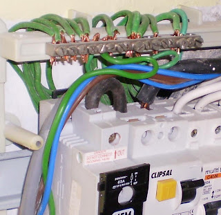
Picture 10 below shows the panel at a slightly different viewing angle. Most of the components inside the panel are mounted on a standard rail and the switch fuse is the component at the far left (your left hand side) of the photograph, with the letters “NEM” on it.
Picture 10 –
Electric panel wiring at a different viewing angle.

The switch-fuse connection terminal for incoming cable is located at the bottom of the unit, and the outgoing connection to ELCB at the top. Therefore, the incoming LIVE cable will come out from the concealed conduit in the wall near the bottom of the panel to terminate at the switch fuse “IN” terminal. You can see that in Picture 10.
However for readers with small computer screen, you can probably see better in Picture 11 below.
Someone out there may say that his or her house panel has another terminal near or adjacent to the switch fuse, which is for connecting the incoming NEUTRAL cable. That is also one of the common practices.
The terminal that the NEUTRAL cable connects to is the neutral link. In this panel, the neutral cable goes straight to the ELCB (which is the component next to the switch fuse). I will talk about the neutral link and the ELCB a bit later.
Picture 11 –
Switch-fuse connection to ELCB

Switch-fuse is actually a combination of a switch and a fuse. Likewise, it is to function as both. You can isolate the supply to the house by switching it to the OFF position. This is what you MUST do if you wish to do some repair works to your house wiring or if you want to replace a faulty circuit breaker.
Part of the switch-fuse is also a fuse inside a fuse carrier. The “60A” means the fuse maximum current rating is 60 amperes. If the electricity current drawn by all appliances and equipment inside the house exceed 60 amperes, the fuse will blow and disconnect the house wiring from the supply at the meter board just outside the house.
Likewise, if there is a damaged wiring that causes a short circuit between cables, the currents can also exceed 60A and the fuse will blow.
This function protects the house wiring from overheating that can cause fires and protect the house electrical system from damage.
After turning the switch-fuse to OFF position, you can actually take out the cartridge fuse inside the carrier. You can then keep the fuse unit somewhere else while working on the wiring.
If someone switches it back to ON position for whatever reason while you are working on the wiring away from the panel, the wiring will not be energized and cause an electric shock, which can be deadly.
From the switch-fuse, a cable connection is made from the outgoing terminal (the top terminal in the picture) to the Earth leakage Circuit Breaker (ELCB). This is the symbol just above the switch fuse symbol in the above schematic diagram (Diagram 4). The smaller blue rectangle has “ELCB” letters inside it.
In your house, you may see that this component is called RCD, RCCB or other names. They are just variations of the technology used to design and manufacture this component. They all work more or less the same way.
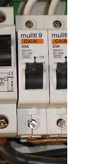
In Picture 10 above, the ELCB is the component next to the switch-fuse, with the letters “CLIPSAL” on it. A closer view of the component is shown on Picture 12 below. This is the same picture as Picture 2 above. I just put it here again for your convenience because this is a long post.
The ELCB protects the users from the risk of electric shocks. Sometimes there is damage to the wiring system or to an electrical appliance connected to the wiring, which causes a leak of electric voltage.
An example scenario may be an injured PVC insulation of a live wiring cable inside a house washing machine. If the exposed live copper conductor (underneath the PVC insulation) somehow touches the metal casing of the washing machine, then the metal casing can be energized to a dangerous voltage level.
Anyone touching the metal casing will suffer an electric shock and may be seriously injured. Death from this type of accidents is common.
The ELCB can detect this leaked voltage and it will trip fast enough to prevent possibilities of serious electrical accidents.
Picture 12 below shows a closer front view of the ELCB unit. You can see from the above two pictures of ELCB that there is a cable connecting the outgoing terminal of the switch fuse (the top terminal) and the top left terminal of the ELCB (Notice that the ELCB has four connection terminals, two at the top of the unit and two at the bottom).
The incoming terminals of the ELCB are located at the top by design. The arrangement helps to produce a neat and very short connection between the switch fuse and the ELCB units. This is an important trait in the arrangement of an electrical system, and the wiring of its electrical components: neatness and efficiency.
Picture 12 –
ELCB unit

From Picture 10 above you can also see a longer cable connected to the ELCB’s second top terminal. This is the incoming NEUTRAL cable, which comes directly to the ELCB from the meter panel. If a neutral link is used together with the switch-fuse, then this connection to the ELCB will come from the second terminal of the fuse link.
There are some details on the ELCB unit that I would like to talk about, but that may make this post too long. I will probably use another new post for that topic.
Now let see the next component in the path of the power flow on the electric panel.
Refer again to the single line diagram in Diagram 4 above. Going upward from the ELCB, the next component in the power path is a thick red-colored line. It is connected to 16 thinner branch red lines with similar symbols on them (labeled “20A SPN MCB”, or 10A instead of 20A).
I took another picture with a different angle again to show you clearly what this thick read line is. See Picture 13 below.
Picture 13 –
LIVE busbar view

Look at the long copper-colored metal piece extending from left to right next to the black cables. This is the actual look of the thick red colored line in the schematic diagram. It is called the LIVE busbar, or the PHASE busbar.
It is copper-colored because it is actually made of copper, the same material that is used to manufacture the cable conductor.
The busbar is used to distribute the electric current to the entire branch wiring in the house. Each of the branch wiring is protected by a circuit breaker, which is the symbol you see on each of the 16 red branch lines in Diagram 4.
How to interpret the circuit breaker symbol
How to read the label next to the circuit breaker symbol, “20A SPN MCB”:
One of the labels says “MCB”. This is an acronym for “Miniature Circuit Breaker”. This is the most common type of circuit breakers used in a house electric panel. In the old days, fuses were used in place if these MCBs. Nowadays fuses are still used for these purposes, but modern homes use mainly MCBs.
“20A” means that the maximum current the circuit breaker will allow into the branch wiring it protects is 20 amperes. If the equipment draws current more than this, the circuit breaker will trip and stop the current flow.
Picture 14 below shows a closer view of one of the MCB units. Observe the label “20A” on it.
Picture 14 –
Closer view of the MCB unit
SPN means “Single Pole and Neutral”. Remember that this is a normal single-phase supply, 240 volt. If an equipment in a house has a high wattage such as a water heater in a big bungalow, with say 8 kW hot water heater, then it will probably need a three-phase supply. Then the circuit breaker that protects its branch wiring would have been labeled TPN, which is “Three Pole and Neutral”.
However, this house electrical panel is only a single-phase type. Therefore, it cannot be used to supply a three-phase equipment.
How is the LIVE busbar connected to ELCB?
You guessed it; it is by one of the black cables coming out from the bottom of the ELCB unit. The other end of this cable is terminated to fourth MCB unit counted from the ELCB position.
The live busbar actually has a number of teeth along its length. Each of the teeth is bent so it can be slotted into the lower connection terminal of the MCB units. You can see this in Picture 15.
Picture 15 –
MCB Connection to LIVE Busbar

At the fourth MCB unit, the live cable from ELCB outgoing terminal and one of the busbar teeth is terminated together at the lower terminal of the circuit breaker.
Therefore, all lower terminals of the circuit breakers in the panel (except the last one at the far right) are connected to the live busbar.
Additional Circuit Breaker
The right-most circuit breaker has a little different story. It seems that this MCB is an additional MCB that has been added later, after the electrical installation work has been completed. Therefore, the busbar length was not long enough to give the extra connection.
So the house occupant added an extra connection wire with an insulation that happened to be green (not a very good choice of color in this case because it can be confused with earthing wires).
We have covered almost all of the components on the electric panel. Now let’s go back to the schematic diagram and check if we have missed anything.
Back to the Schematic Diagram – Diagram 4
As you can see in the diagram, after the MCB symbols there are only thin red lines, which are what we call final circuit wiring. These wiring cables go to the wall socket outlets and the wall switches in the house.
The diagram also indicates the sizes of the wiring cables. I have shown how to interpret those labels earlier for the incoming cables. So now, the interpretation method is also the same way.
Are these all the components on the electric panel? Not quite.
The neutral and earthing busbars
Look at Picture 10 again. Above the ELCB unit, you can see a different type of busbar. This one has a number of screws on it for the purpose of cable terminations. As you can see, there are a number of green cables connected to it. That is because it is the grounding busbar.
Picture 16 –
Grounding Busbar
I will not elaborate much on this topic today because this hub will then be too long. I will pick up on the grounding topic in another post. Electrical grounding is a major topic in electrical works.
Suffice to say for now that the ground wiring is like the nervous system for the electric shock protection in your house wiring.
If a house electrical ground wiring is not working properly, a faulty appliance such as a washing machine can cause electric shock injuries and electrocution in the house. The risk of fatal accident is very high. It is that simple.
This can happen even if the ELCB or RCD unit is tested regularly and it seems to be healthy.
The neutral busbar
Far to the right side of the earthing busbar is the neutral busbar.
Observe carefully the wiring connected to the outgoing circuit breakers (i.e. the MCBs). There is only one wiring cable there, which is the LIVE cable.
Picture 17 –
Neutral Busbar

One cable is not enough to make a complete loop (Remember the basic principle of electricity in the beginning of this article?). So there must be a second cable, the NEUTRAL cable, which comes out of this panel for each of the circuit breaker, right?
Right. The NEUTRAL wiring cables are the black cables connected to the neutral busbar. One black cable need to be installed for the outgoing wiring of each circuit breaker. We have 12 outgoing circuit breakers on the panel.
Therefore, there must be 12 neutral cables connected to the neutral busbar.
The same number should also be for the green wires connected to the grounding busbar. If the number is less, then the wiring needs to be checked by an electrician.
The number of NEUTRAL connections must equal the number of circuit breakers
What if the number of the green and black cables connected to the busbars are smaller than the number of MCBs on the electric panel? Can the electrical system work properly?
Yes, it can with certain conditions. However, it is not a good practice and it is not recommended. So don’t do it even if you are a good electrician.
This issue is a more advanced subject. So I will save it for a different article. Beginner readers may get confused if I mix them up here.
Is the Grounding Busbar Grounded?
With all the above pictures, you can see that the LIVE busbar is connected to the LIVE incoming cable (at the fourth MCB from left). The NEUTRAL busbar is connected to the neutral incoming cable below the neutral busbar (better seen in Picture 17).
The GROUNDING busbar or the EARTHING busbar, which is part of the central nervous system for the house electric shock protection, needs to be effectively connected to the main earth mass. Without this connection, the shock protection simply will not work.
Can anyone guess the connection cable to the earth mass from the pictures above? I can’t either.
But don’t worry. I have actually tested the wiring and the earthing connection worked properly. I just didn’t have the time to find out which of the green wiring cables actually connects to the grounding electrodes outside the house.
I think the above covers all the important components on the house electric panel. If I have missed anything, someone please let me know. I will send an update.
One more thing before I close this post. The electric panel in the picture is not exactly the same as the one in the schematic diagram. Some readers may have already noticed this by the number of miniature circuit breakers (MCBs) on the panel.
However, these two panels are very similar. Only the number of final wiring circuits is different.
You can see more pictures of electrical installations at this post,
Temporary electrical installation pictures.
You can also see more pictures of electrical wiring by visiting this post,
Pictures of electrical wiring.
Copyright http://electricalinstallationwiringpicture.blogspot.com 1- Phase ELCB connection pictures

.jpg)


