Showing posts with label Underground armored cables. Show all posts

Saturday, February 11, 2012

Backhoe, the cable trench excavator

Backhoe, the multi-purpose, versatile machine can be found anywhere there is a construction work under way. It is also the most popular type of machines for excavating electric cable trenches.

Thus this machine deserves a post of its own.

Picture 01 – A backhoe being used to handle an electric cable drum
(Click on the picture to enlarge it)

================= RELATED ARTICLES: Electric Cable Drum Pictures |  Underground street light cables |  Underground electrical manholeCompound lighting storage yard  | Compound Lighting Installation Pictures  | Feeder pillar single line diagram  | Bollard light pictures  | Feeder pillar hazard pictures  | Compound lighting foundation size
=================

Observe the heavy duty steel chain and the steel pipe being used to lift the wooden cable drum.

A backhoe basically consists of three major sections as shown in the following picture.

Picture 01a – The three sections of a backhoe
(Click on the picture to enlarge it)

There are basically three sections of a backhoe: the tractor section in the middle, the front loader section, and the “backhoe” section.

The tractor section is the driving force and the controller section. This is the moving vehicle with four tires and it is here that the driver sits. You can see the driver (i.e. the machine operator) sitting under the metal hood at the center of the machine in the above picture.

The backhoe operates the rear and the front tools (the rear shovel bucket and the big front loader bucket) using two controllers at the tractor section: the controller for the front loader is at the front of the driver’s seat, while the controller for the rear bucket is located behind the seat.

Usually a task requires the operation of only the front or the rear bucket at a time.

Therefore if a task mostly requires the operation of the rear bucket such as excavating a narrow trench, the operator would just swivel the chair around.

Even though the operator is able to work comfortably facing both the front and back of the machine, the operator would be facing the front loader during normal driving. That is the right side of the picture in Picture 01a above.

Picture 02 – Another view of a cable drum lifting scene
(Click on the picture to enlarge it)

Picture 03 – A backhoe repairing a road ground level
(Click on the picture to enlarge it)

Picture 04 – Backfilling a cable trench with the excavated earth
(Click on the picture to enlarge it)
Picture 05 – Backfilling a cable trench
(Click on the picture to enlarge it)

Another picture showing the machine pushing the excavated earth to backfill the cable trench.

Observe what appear like two lengths of cables coming out of the cable trench at two locations.

These two locations are among the locations of the road light poles.

What appears like two lengths of cables coming out of the trench are actually one single length of cable that has been pulled out to form a loop at a road light pole.

A single circuit from a feeder pillar is normally designed to supply six poles regardless of the wattage of the lamp at each of the six light poles.

The first five of the poles starting from the supplying feeder pillar would have the cable loop coming out of the cable trench like in the picture.

The last pole in the circuit (i.e. the furthest from the supplying feeder pillar) would have just “one cable length” coming out of the trench, unlike “two lengths” as in the picture.

Beginners who are still confused about the “two cable lengths” should look at the following picture. It should clear the issue.

Picture 06 – A light pole foundation and the looping cable ready for the installation of the light pole

(Click on the picture to enlarge it)

One more point that beginners should note here is that the underground road light cables are installed BEFORE the installation of the light pole foundation.

I will upload some pictures on the installation process of the light pole foundation in a future post.

Picture 07 – A cable drum identification tag containing some details of the cable including the cable drum weight
(Click on the picture to enlarge it)

This picture shows a cable drum identification tag. The drum carries 310 meters of 95 millimeter square multicore XLPE armored cables.

It weighs 2030 kilograms. Therefore it is not that easy to handle the cable drum (other than rolling it, which is a futile attempt most of the time at a construction site) and install the cables into a cable trench without the assistance of a machine.

Copyright http://electricalinstallationwiringpicture.blogspot.com/ Backhoe, the cable trench excavator

Underground street light cables

This post gives you a few pictures showing the process of installing underground street light cables.


Picture 01 – A contractor’s site supervisor giving instructions during backfilling of an underground cable trench

(Click on the picture to enlarge it)

================= RELATED ARTICLES: Electric Cable Drum Pictures |  Underground electrical manholeCompound lighting storage yard  | Compound Lighting Installation Pictures  | Feeder pillar single line diagram  | Bollard light pictures  | Feeder pillar hazard pictures  | Compound lighting foundation size Architectural Lighting
================


Type of activities: Installation of underground cables for street lights

Location: Internal road of an office building complex

Type of building: Multi-storey office building

Other description:

The picture above was taken during the installation of underground street lighting cables.

This project was the construction of a considerably large multi-storey office building complex.

Being a government office building with large numbers of public service counters, there were a sizeable parking lots around the building.

Therefore a considerable number of carpark lighting and street lighting had to be installed in this project, and all cables to the lighting poles were installed underground.

As usual, for projects like this I always insist that at least two and a half feet of cover is provided above the top underground cable.

This means that the depth from the completed surface of the ground or the internal road to the top of the cables is not less than two and a half feet (or 750 millimeters).

This is to ensure that the cables are not damaged from the force at the ground surface from moving vehicles and other loads.

Repairing damaged underground cables can be a messy and costly affair. It is embarrassing too, if the building have just been commissioned.

In actual installation, however, this cable depth from the finished ground level cannot always be met because of either technical difficulties or excuses cooked up by the cable laying contractor to keep the excavation as shallow as possible.

The deeper the depth of the cables, the more excavation works that need to be done. After the cable installation is completed, the excavated cable trench need to be backfilled and compacted. In short, the deeper the cable trench is, the more work and time is needed and therefore the cost is more.

A cable laying contractor would always try to find some reasons to reduce the cable trench depth to as shallow as possible. Among the usual reasons is the presence of underground sewage pipes, water supply pipes, road crossing culverts, etc.

Some of these reasons are valid, some are just excuses.

However, under many circumstances, the two and a half feet depth of cover just cannot be met especially for street lighting works within a building compound.

In these cases, the solutions are adopted on a case by case basis.

In general, a cover as shallow as 450 mm or 500mm can still be adopted depending on the usage of the finished ground surface above the cables.

If the maximum depth of cover that can be given is less than 450mm, then the cable can be installed in underground steel conduits or PVC conduits encased in concrete.

These two methods are conventional methods that have been around for many years.

Whatever the solution adopted for a particular situation, the reliability of the installed underground cables should be given a top priority because repair works on underground cables is relatively costly and messy.

Below is a rough guide of the process involved in the installation of underground street lighting cables. This only gives an overall view of the process. I will upload a cross section view of the cable trench in a future post.

Before any work on the underground cable installation commence, the contractor should obtain the latest approved design from the design consultants.

This is not just drawings for the street lighting and other underground electrical cables. Preferably the layout drawings of all external services need to be studied.

Normally this sort of design coordination is the responsibility of some engineers from the design consultants with the input from the main contractor’s site coordinators.

However, a building construction work involves many parties and many people. Along the line, it is highly likely that someone overlooks something or simply makes a major mistake.

In the end, the cost of the rectification that resulted from the mistake is absorbed by the cable laying contractor or the electrical contractor first.

Attempts can be made to recover the losses from the party that make the mistake. However, it usually not easy to recover the additional cost from mistakes such as this.

Therefore the best approach is to make sure that the drawings used are the latest design drawings for all underground services, and the latest architectural drawings for the external works are studied before the cable trench excavation commence.

Before underground cables are laid, the cable trench must be thoroughly inspected. There should not be any debris and sharp object in the trench.

A layer of clean sand approximately 3 inch thick shall be installed at the bottom of the trench before the cables are laid. The three inch sand bedding is the thickness after compaction, not the sand thickness while it is being spread over the trench bottom.

The following picture shows a worker compacting the sand bedding with a mechanical rammer.

Picture 02 – A worker compacting the sand bedding with a mechanical rammer


(Click on the picture to enlarge it)

Observe the width of the mechanical rammer. It is about 12 or 14 inch.

The width at the bottom of the trench is only about 2 to 3 inch wider than the rammer width. This rammer size is about the smallest that I have seen. I have seen a few bigger sizes, but this is about the smallest one.

If the “bucket” used by the excavation machine to dig the cable trench is too narrow, this mechanical rammer might not have enough clearance to do the compaction.

In one of my earlier projects, the electrical contractor used a very small bucket to dig excavation trench for a street lighting underground cables.

Because the route of the cables ran around tight corners at a number of locations, a narrow excavation bucket was more convenient. The work could also be completed faster.

On top of that, the amount of sand bedding that needs to be used below the cables and sand cover above the cables could be much reduced (i.e. cost saving) if narrower bucket was used.

The contractor started work on one Friday afternoon and by Monday morning, all cables had been laid. In the Monday morning, they called for a formal inspection so that they could commence the backfilling work.

Too bad. I told them that the sand bedding had to be compacted to 3 inch thick, not just spread over the trench bottom to a three inch thick.

Compacting the sand was one thing, but the cable trench was too narrow for even the smallest mechanical (about the size in the above picture) rammer to go in.

I did not know exactly why the electrical contractor dared to gamble like that on that occasion. They already knew I always insisted on following the specifications when it came to underground works in that particular project (which was also a government office building project).

In the end, they had to take out all the cables that had been laid in the trenches and re-excavate the whole length of the cable trenches again with a bigger excavation bucket.

Double-work, and doubled the cost.

The picture below shows an excavation machine used to do excavation for cable trenches. Here we call this machine a “backhoe”. It is not an “excavator”. An excavator is a much bigger machine.

Picture 03 – An excavation machine commonly used in excavation of cable trenches

(Click on the picture to enlarge it)

During an underground cable laying, the cables should be laid on the sand bedding in an orderly manner. They should not cross or overlap each other.

After the cables have been laid and properly arranged, another layer of 3-inch clean sand should be laid over the cables as a cover.

This 3-inch sand cover also should be the thickness after compaction.

In some projects, the contract specifications do not specifically say that the sand bedding below the cables should be compacted first before cable laying process.

In cases like this, I might choose to allow the contractor to do the compaction after placement of the 3-inch sand cover.

If this method is adopted, then care should be taken so that the workers keep the cables at approximately the middle of the 7-inch compacted sand thickness (3-inch below the cable plus 3-inch above the cables plus one to one and a half inch cable diameter).

In the picture below, the sand bedding and the sand cover was being laid in one go and later it would be compacted.

Picture 04 – Sand bedding and cover being placed in one go inside a cable trench

(Click on the picture to enlarge it)

Beginners should not get confused here. Sand “bedding” is the word used for the layer of sand below the cables.

The sand “cover” is the layer above the cables, that covers them.

The words “bedding” and “cover” are widely used across many engineering disciplines that involve underground works.

After compaction of the sand cover, a layer of protective covers of some type should be place over the sand, right above the cables with overhang of at least one inch on each side of the cables.

In the old days, clay bricks are used as the protective covers.

The purpose is to let people doing excavation work later in the vicinity of the underground cables that once the excavation uncovers these clay bricks, it should warn the excavation operator that there are electrical cables underneath and therefore he should proceed with caution to avoid damaging the cables.

Later, about 15 or 20 years ago, there appeared some common opinions among electrical contractors are that the clay bricks could not protect the cables.

Often excavation operators did not take the uncovering of the clay bricks as a warning of electrical cables underneath because the in some locations the clay bricks exist everywhere in the ground as leftovers from previous construction and also from wastes.

The cost of repair to damaged underground cables can be substantial to small contractors that do external works involving excavation.

Simply said, the use of clay bricks could not protect the electrical cables. They could only warn of the existence of electrical cables underneath and often they were not very effective in doing that.

An alternative came in the form of thin PVC tapes that are supplied in the form of coiled long sheets.

The principle behind this method is that the PVC tape cannot be broken easily even when stretched and pulled out of the ground by an excavation machine. A warning telling the type of cables underneath (whether electrical cables, telecommunication cables, etc) are printed throughout the length of the PVC tape.

This method is still practiced today.

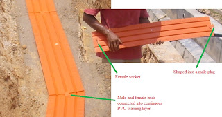
However, another alternative appeared a few years ago in a form orange-colored, thin interlocking PVC plates.

This method has been used in most projects that I handle nowadays and is shown in the following picture.

Picture 05 – A worker placing PVC protective covers over the sand cover

(Click on the picture to enlarge it)

Each piece of the PVC plates is embossed (not printed) with suitable DANGER warnings. The printed warning types are still available today, but I always insist on the embossed types because a low quality printed warning can get eroded over time, or due to improper handling during installation.

Picture 06 – PVC protective covers

(Click on the picture to enlarge it)

After the placement of the protective PVC covers, the cable trench is backfilled with good earth and compacted every 6 inch until the finished ground level.

It is also a good practice to top the earth up by about 2 inch above the existing level to allow for settlement of the newly backfilled cable trench.

Often the civil work contractor would continue with the ground finishing work or the road work after the electrical contractor has completed the underground cables installation. They may not insist on the two inch top up.

However, the compaction of the sand layers and the earth backfilling are always an issue between the electrical contractor and the civil or the main contractor of a project. Therefore it is always wise to stick to the requirements of the contract as the minimum.

Many times even the specifications of the contract are not tight enough which leads to disputes between contractors after the cable laying has been completed.

Worse still if the dispute appears just before the handover of the newly completed building to the owner, or just after the commissioning and operation of the building, when some settlement on the finished ground or the finished road begin to appear.

To say it simply, this is one of those areas where a wise judgement on the part of the supervising engineers is needed.


Copyright http://electricalinstallationwiringpicture.blogspot.com/ Underground street light cables

Wednesday, August 18, 2010

Underground electrical manhole

The picture below shows an electrical manhole intended for underground installation being unloaded from the transport truck.

Picture 1 – The electrical manhole being unloaded


================= RELATED ARTICLES: Electric Cable Drum Pictures | Underground street light cablesCompound Lighting Installation Pictures | Feeder pillar single line diagram | Bollard light pictures | Feeder pillar hazard pictures | Compound lighting foundation size  | Electrical installation pictures
=================

Most building works require at least one or two underground electrical manholes. That is because a building of significant size usually require a few hundred amperes of electric current at low voltage (i.e. 240 volt, 3 phase current).

Above a few hundred KVA (kilo-volt-amperes), the electricity supply authority usually delivers the electrical power to the consumer loads at higher than 240 volt, usually at 11,000 volts.

(Note: 100 amperes x 240 volt x 3 phases = 24,000 VA x 3 phases = 72,000 VA = 72 KVA. For readers who are intimidated by the KVA term, this is what KVA is. That is measure of electrical power delivered to a building. It is also the most common unit used in specifying the size and rating of electrical equipment and switchgears.)

Okay, back to the electrical manhole.

When the supply is at 11,000 volts (i.e. 11 KV), high voltage cables installed below ground level (i.e. underground) is the most popular method of electricity distribution unless the building is in remote areas such as the countryside.

So, in building works, we need at least one or two of these manholes to bring in the authority cables from outside the boundary of the building works to the electrical substation inside the building compound or the inside the building itself.

Picture 2 – The electrical manhole at a closer look


Notice the note I put in the picture saying “precast conduit sleeves”.

These sleeves were made in the factory to facilitate the connection of underground electrical conduits carrying the cables to the manhole.

If these openings on the concrete walls of the manhole are not made in the factory, then the openings have to be manually made at site using electric hammers etc.

Most of the times, some modifications are still needed because the high voltage cables are usually large and they are difficult to turn and bend.

The underground conduits may also not arrive at the manhole at the same levels of the precast sleeves. If they do, they may not all be at exactly 90-degree angles to the manhole walls.

This means some hacking still need to be done to the precast sleeves.

I forgot to tell you that the precast sleeves are made to accept 150 mm diameter of electrical conduits. It is a common practice to use 6 inch diameter underground conduits for electrical distribution cables.

Smaller sized conduits are also used, but they are generally for underground street lighting cables and compound lighting cables inside the building compound.

In these cases, 4 inch diameter conduits are used and they are installed when the compound lighting cables need to cross under internal roads.

I did not mean this post to be discussing underground cabling works. I just wanted to show some pictures of electrical underground manholes so that I can just refer to this post when talking about underground electrical manholes.

However, the above brief issues on the manhole are necessary to give some meaning to the pictures here.

So for the readers with more advanced knowledge on these things, please be patient with me. This blog is for beginners.

Picture 3 – An installed underground electrical manhole


This is how it looks after the manhole has been installed. Even though it is called “underground”, the manhole is not really totally “buried” below ground.

The exposed part of it is still visible and accessible at ground level.

Picture 4 – Manhole cover


This is the top of the electrical manhole, which is leveled to the finished ground level, exposed and accessible for access.

Observe carefully that there are 4 pieces of the manhole cover. These covers are made of reinforced concrete. So they are very heavy. Breaking it into 4 pieces make it easier to be opened by manually hand-lifting it.

Even at that smaller-sized, it usually takes at least 2 normal-sized persons to lift open a single piece after a few years. Yeah. I know. Hulk Hogan may only need two fingers to do it).

Picture 5 – The base of the manhole pit


You cannot just dig a hole of sufficient size in the ground and plant in the concrete electrical manhole.

If you do that, sooner or later one of the manholes would sink in deeper into the ground, or get tilted enough to break the underground electrical conduits and possibly damaging the underground cables.

When that happens, you would then need to carry out excavations when one of the cables need repairs or when additional cables need to be installed along the same underground route.

In fact this is the very reason the underground electrical conduits and manholes are used: to facilitate maintenance, repair and upgrading of the underground electric cables in future, long after the building is completed and occupied.

At the base of the opening in Picture 5 is a layer of sand. It is a practice to put some river sand at the base and compact it to give about 4 inch thick after compaction.

Of course, before that sand is poured in, the ground at the bottom should be firm and solid. If the soil at the bottom of the pit has been spoilt because of water accumulating there, then pit bottom must be excavated further to remove the spoilt earth. This also means more sand may be needed as the volume to be refilled would then be larger.

There is one very important I would like readers to note, especially those directly involved in construction.

You must NEVER allow the contractor to just install the manhole without first being inspected by someone responsible.

If the preparation of the base of the pit is not good enough, the manhole may sink in sooner than you would hope for. To repair it would require re-excavation works which are usually messy.

Someone may need to take the blame. It is not always easy to cover up mistakes like these.

Picture 6 – Excavated pit for an electrical manhole


I just include this picture to make my point above.

This particular opening in the ground was made in front of an electrical substation. It was supposed to be for the manhole of the same type and size as shown in the pictures above.

However, for some reasons the delivery of the factory-manufactured manhole did not arrive. So the opening was just left there. Sooner or later it would collect rainwater, which it did as can be seen in the picture.

Suppose one day the contractor calls you and say that he has finished installing the underground electrical manhole in front of the substation. With that the electrical authority can start pulling in the high voltage electrical cables.

In two weeks, the substation would be energized and the new building would have permanent electrical power that would also facilitate the testing and commissioning of all the electrical and mechanical services in the building, which has been delayed due to the delayed energization of the electrical substation.

This was a good news, and a reason for celebration. Of course, the real celebration should be AFTER the actual energization of the substation.

Being the one giving the good news to you, the contractor has made a dinner reservation at a nearby six-star hotel. It is a celebration and YOU are the man.

What would you do?

What would I do? I would accept the invitation to the dinner. After having a very nice meal and laughs, I would excuse myself earlier than normal. On the way out, I would tell the contractor to immediately start the arrangement to remove the installed manhole and prepare again the manhole pit in front of the substation.

Only after I say okay he would be allowed to re-install the manhole.

What would you do?

Copyright http://electricalinstallationwiringpicture.blogspot.com Underground electrical manhole

Saturday, April 3, 2010

Feeder pillar single line diagram

Today I will show the readers a simple schematic diagram of a compound lighting feeder pillar. It is for those who need to know a few basics of a compound lighting system in order to carry out other tasks such as architectural landscape design and costing works, etc.

There are also a few pictures of feeder pillars so the single line diagram will make some sense. If you need to allocate some space for the feeder pillar plinth, then I have already uploaded a few diagrams towards the end of this post. They should give you enough information to solve the technical problems.

Diagram 1 – Single line diagram of a small feeder pillar for compound lighting


================ RELATED ARTICLES: Electric Cable Drum Pictures | Underground street light cablesWeatherproof 13A switched sockets | Metal-clad socket outlet | Compound lighting storage yardCompound Lighting Installation Pictures | Bollard light pictures | Feeder pillar hazard pictures |  Compound lighting foundation size  | Electrical installation pictures Architectural Lighting
================


A feeder pillar single line diagram is similar a house electrical panel schematic diagram with the addition of an automatic time switching circuit added.

In the single line diagram, the time switching circuit is the circuit portion towards the top left corner of the dotted rectangle box. The sub-schematic is shaded into lighter grey.

Diagram 2 – Timer switch circuit


There are three items I wish to highlight to readers at the time switching circuit: the time switch, the contact coil and the “SWITCH BY PASS”.

The TIME SWITCH

First, the time switch. This is drawn with a symbol of a circle with the “TS” letters inside it.

A time switch is a component that is common to all street lighting and compound lighting. Its purpose is to eliminate the need for human actions to turn “ON” and “OFF” the lighting at the intended operation hours.

For example, the external carpark of a shopping complex may need to be lighted up at 7 every evening and be turned off at 3 A.M.

So this ON and OFF times can be set at the time switch inside the feeder pillar.

A human operator may miss the exact time one day, which can leads to complains by customers, but a machine would not forget. They may break down, but a properly cared machine can be much more reliable than human most of the time.

In large installations, even indoor lights are sometimes installed with similar automatic timers. It is not just for good service, but also to reduce operating costs as the setting of the timer can be authorized to only selected individuals of the organization.

One hour of delayed switching off the lights every night can mean significant additional dollars monthly on electricity bills in large installations.

The SWITCH BY PASS, or MANUAL BYPASS SWITCH

Another important component here is the normally open switch that is labeled SWITCH BY PASS in the single line diagram.

In many drawings, it is called MANUAL BYPASS SWITCH, which I think is more appropriate and more accurate. But one of my draughting lady tends to prefer SWITCH BY PASS label so much that I need to let her have her own way.

The manual bypass switch is used for maintenance or trouble-shooting works. It simply bypass the time switch to ON or OFF the external lighting or street lighting.

For genuine beginners, observe that the bypass switch is connected in parallel with the contacts of the timer relay (Diagram 2 above). With this configuration, either contact in a closed position would energize the contact coil and turn on the external lights.

Often the switch is also the key-operated type so that the ability to bypass the timer can be restricted to only authorized individuals.

The contact coil

This is the third component in the time-switch circuit.

The load currents to the lighting cables are usually higher than the current that the timer contacts can handle. Therefore, another coil with heavy current contacts need to be provided to switch the heavy currents.

That is the purpose of the coil with a symbol of the circle with the “C” in it.

Observe the dotted line connecting the coil to the three contacts at the lighting load circuit.

That is all I wish to say on the timer switch circuit today. For electrical-based readers, the above explanations are never necessary. However, for no-electrical readers, these details on the schematic diagram would probably confuse many of them

Now let’s go through a few more components inside the feeder pillar cubicle that may confuse the readers from understanding the simple single line diagram.

The cubicle lighting

Towards the right edge of the dotted rectangle, there is a fuse labelled “20A SPN S/F”. You may not see this extra component inside a normal distribution board.

It is used to supply a fluorescent light inside the feeder pillar. As you know, the feeder pillars are installed outside. Any problem to the compound lighting would probably be noticed at night, when the lights are supposed to function.

Because of that, maintenance, trouble-shooting or repair works need to be done in the dark outside. The lighting from the compound lights would not be enough for work inside the feeder pillar. Additional light lighting is needed and that is what the fluorescent light fitting is for.

The socket outlet is also provided for the same purpose (i.e. to operate the tools for the maintenance work).

These are the accessories for the street light feeder pillar or compound lighting feeder pillar.

The timer switch circuit is actually a control circuit.

Other that that, the circuit schematic is almost similar to a simple house schematic.

The main schematic

Now let me give a short brief on the main schematic, the power circuit of the system.

As explained above, the dotted line rectangle represents the physical area of the feeder pillar cubicle.

Components and symbols located inside the dotted rectangle means they are located inside the metal cubicle. That is how to interpret an electrical diagram of this type.

The electric supply is taken from the Consumer Main Switchboard as shown at the lower part of the diagram.

A short introductory brief on armored electric cables

One length of underground armored cable is used. Underground means the cable is installed inside the ground about 3 ft below the surface.

Armored cable cost much more because of the steel wire armor protecting the cable from physical damage. The letters SWA in the cable tag “XLPE/SWA/PVC” is an acronym for “steel wire armor”.

“XLPE” at the front means the insulation of the cable conductor. When we say a cable, the terminology is actually not precise enough.

In this case, inside the incoming supply cable there is actually 4 inner cores each with an electrical insulation. Therefore, each of the four insulated inner cores (the inner core is usually made of either copper or aluminium) is a complete electrical cable by itself.

The four of them are bunched together to make it easier to run and it can reduce the cost. We can actually use 4 independent cables instead of one cable with 4 inner insulated cores.

The XLPE label mentioned above indicates the type of insulation of each of the inner cores.

When these cores are bunched together in a bunch like these, an outer insulation is again extruded or layered over the whole bunch, making it look like a single cable. It is actually 4 cables that are bunch together.

The outer insulation is called outer sheath.

If this cable is to be installed underground, it is always better and always considered necessary to provide something strong over the cable in case an excavation work accidentally hits it.

That is why the steel wire armor wrapped around the cable spirally all along the cable length. The armor protects the cable physically.

Then in order to protect the armor against corrosion and other degradation, another layer of insulation is applied over the steel wire armor. Most of the time, it is of PVC (poly vinyl chloride) materials.

That is the label “PVC” on the right of the cable tag.

I did not finish the XLPE part, did I?

What is XLPE?

The XLPE is just like the PVC, but is more expensive and of better quality. That is why it is used only at the inner core of the cable. The PVC material can be used instead of the XLPE, and it will work just fine.

But with XLPE, the inner cores can usually carry higher current for the same inner core size.

I know many readers already now this, but I always wanted to put it down somewhere so I can just give a link whenever an issue requires a further explanation on this cable topic.

What is 1 – 25 SQ. MM. / 4C?

“4C” – I just explained above, the 4 inner cores. If there are 5 or 3 cores inside, then it would have been 5C or 3C accordingly.

“25 SQ. MM.” – I mentioned about the size of each inner core, the copper or aluminium material underneath the XLPE insulation. This is the size. It is always in the form of net or real cross-section area. This means if an inner core is constructed of several smaller cylindrical copper wires, then the total cross-section area of those individual wires is taken and used to indicate the size in square millimeters.

I am following the British or European Standards here.

“1 – “ … well this mean one length of the 4-core cable is used here. We can use 2 lengths which will give us 8 cores of same sizes. They are installation conditions that may force us to do that, which is a more advanced topic. In that case, it would have been written like this:

“ 2 – 25 SQ. MM. /4C XLPE/SWA/PVC”.

That is all about the incoming cable.

The feeder pillar isolation switch

“60A TPN MCCB” – this is the isolation switch. The type of switch used is MCCB (moulded case circuit breaker).

So this switch is also a circuit breaker. It can automatically switch OFF when there a fault inside the feeder pillar cubicle or the cables going to the light poles.

You can actually use a switch and a fuse instead of the MCCB. That is the protection used to supply the cubicle fluorescent light explained above.

The outgoing circuit protection

Going downstream of the power flow path, you can see the outgoing circuit breakers (i.e. 20A SPN MCB) that are used to protect the cables going out to the light poles.

Six MCB’s are installed here.

Three are spares however. No cable is connected to the spare MCB’s even though there is a red line drawn to each one of them. This is the practice when drawing these types of electrical diagrams.

Each of the three MCB’s that are electrically loaded (they have electrical loads i.e. the lights connected to their outgoing cables) has 6 compound light fixtures connected to it.

Each of the fixtures is 70 watt. So we have 6 x 70 = 420 watt connected to a 20A circuit breaker. That is how to read the diagram.

The type of the compound light fitting is HPSV (high pressure sodium vapor).
(UPDATE: A low-pressure sodium type of street light or compound lighting would give you the yellowish light like those seen on the highway. Not a nice color but this type is very energy efficient.
But the high-pressure sodium vapour (HPSV) type that is used here has a good "color rendering". This is the terminology lighting people use to say that the colors produced by a lighting fixture allow human to distinguish different colors easily and correctly.
The low-pressure sodium lamp as mentioned earlier is very energy efficient. However, the yellowish color that it produces have a very poor "color rendering". Have you ever seen the color of your own skin under one of these lights at night? )

The number of lights connected to each outgoing circuit is quite standard for compound lighting. Most installations only connect 6 lights to a circuit regardless of the MCB rating or the rating of the light fixture which usually varies between 70 watt to 250 watt..

So you can actually know how many outgoing circuits you need once you know or estimate how many lights would be installed inside the building compound.

Now let us look at a few of the feeder pillar pictures

Picture 3 – Feeder pillar for compound lighting


This is for a compound lighting system at a public building. Notice the concrete plinth that it is sitting on.

Here there is also an additional power socket installed but it is located outside the cubicle. Therefore, it has to be of a weatherproof type.

Picture 4 – Outdoor power socket


When you install electrical equipment outside of a protected room, under the rain and hot sun, it need to be of a weatherproof type.

Electric voltage inside an electrical equipment and appliance is very dangerous. It can easily kill people.

Every knows that. But when it is installed at a location where there is a possibility of water seepage into the enclosure, then the equipment become extremely dangerous.

That is why when we say weatherproof, the design, manufacture and installation must comply to a certain criteria and quality standard.

The category of degree of waterproofing is graded by what is called IP rating.

Picture 5 – Weatherproof socket IP rating


The 13A power socket here is rated as IP 66. The letter IP stands for Ingress Protection. I think that was how it came to be.

The first number after IP is the grade of protection against ingress is dust and solid objects into the enclosure.

The second number shows the class of protection against harmful ingress of water. The number 6 in this case means that the outdoor socket unit has been designed and manufactured to withstand against water jets to the unit from any angle.

This is important because being installed at a landscape area there are possibilities of strong water jets when the caretaker is watering the landscape garden.

A cleaning work of the compound area after parties and functions may also expose the unit to water jets.

IP Rating of the feeder pillar metal enclosure

I have spoken of the need to waterproof the outdoor socket outlet. The feeder pillar metal cubicle is even more important to be waterproofed.

I did not take the photo shot at the manufacturer label of the feeder pillar. However, I think the IP rating of the above feeder pillar would not be less than IP 56.

This means that the protection against the ingress of water is of the same grade as the 13A socket.

However, the protection against the ingress of dust and solid objects is probably at grade 5, which is one step lower than that for the socket.

At grade 6, the enclosure would not permit any ingress of dust at all. But at 5, some very small dust particles may still be able to enter the feeder pillar enclosure without any harmful effect to the operation and quality of the components and installation inside the cubicle.

The photographs above was taken of an existing feeder pillar for a compound lighting. The other 2 more below are from a new installation that is still in progress.

Picture 6 – New feeder pillar installation in progress


You can see that the underground cables to and from this feeder pillar are not yet terminated.

This unit seem to be much bigger than then existing one shown above. However, that does not necessarily mean it carries more electrical load or anything.

It only means the cubicle design provides more space inside for the access to the components and parts. Usually a bigger unit cost more even if the schematic design used to manufacture them is the exactly the same one.

Picture 7 – Cable entry to the feeder pillar


For readers who are looking for some details on the construction of the feeder pillar, bellow is an example. These 4 diagrams provides you enough measurements to locate the unit precisely at a tight space in a building compound.

With the single line diagram in Diagram 1 above, you can even get a pretty accurate estimated cost from the manufacture and supplier if you allow them to use their standard parts and components.

Diagram 8 – Feeder pillar front view


Diagram 9 – Interior component layout


Diagram 10 – Side dimensions


Diagram 11 – A section showing how the components are to be arranged and routed


Copyright http://electricalinstallationwiringpicture.blogspot.com Feeder pillar single line diagram