Showing posts with label Carpark lighting lighting. Show all posts

Thursday, July 29, 2010

Compound lighting foundation size

I am sending up the following three images on compound lighting pole foundation details to fulfill a request by a friend earlier today.

Image 1 – The overall diagram of a five-meter lighting pole


================  RELATED ARTICLES:  Electric Cable Drum Pictures | Underground street light cablesCompound lighting storage yard | Feeder pillar single line diagram | Bollard light pictures | Feeder pillar hazard pictures | Compound Lighting Installation Pictures  | Electrical installation pictures Architectural Lighting
================


He was supervising a construction job of several pumping stations at a remote location in the countryside.

The project was worth just above ten million (I think that was what he told me a few months ago), so the budget for the supervision team was not that high.

Being a little bit out of the way, not many engineers would be interested to fulfill the vacancies for the resident engineer posts with the salary the engineering consultant could afford to pay.

However, the construction works still have to proceed and the project still need to be completed and delivered on time. No main contractor would want to risk any possibility of delays especially in a design-and-build or a turnkey contract.

As usual, the best solution in this sort of situations is to employ just one resident engineer to supervise both the electrical parts of the work.

This way the salaries meant for two resident engineers (i.e. for electrical and mechanical resident engineers) is paid to just one making the vacant post much more attractive.

That was the kind of post this friend of mine took and he got a pretty good offer to supervise a relatively small jab.

Naturally there is a problem, however. He is a mechanical engineer who needs to look after all the electrical works also.

He needs a friend’s help now and then to ask for some free professional advice.

That was what happened today. He needed to advise the electrical contractor on the size of the foundation for the compound lighting pole.

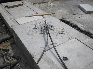
Image 2 – The blow-up view of the foundation for the 5 meter compound light pole


There not much that I need to elaborate on this concrete foundation. It’s just a simple plinth with the size of 500mm x 500mm x 900mm.

Notice the mounting bolts and the high impact PVC pipe cast into the concrete.

This image above shows just one uPVC pipe sleeve. Normally you would want at least two sleeves: one to the left and one to the right because cables to the light poles are usually looped in and out from the previous pole and then to the next pole.

So the image above if for a pole that is on the end of the loop.

Observe also that the dimensions of the concrete base are sized at bit larger than the base plate or the bearing plate of the steel pole (See Image 3 below).

Image 3 – Bearing plate dimensions


This is to give enough clearance around all the mounting bolts so that there is enough strength of the concrete to withstand the load imposed to each of the bolt.

The size of the foundation above is actually one of the standard practices that I know for the light pole height shown above and you should have nothing to worry about.

Of course the type of the soil is a major factor. So if you have doubts just call the light pole supplier or just ask the civil engineer. This is just a simple common issue for them, so you should be able to get an immediate confirmation.

I have been using this size in all my projects and never had any problem.

See you again the next time.

Copyright http://electricalinstallationwiringpicture.blogspot.com Compound lighting foundation size

Sunday, March 28, 2010

Compound Lighting Installation Pictures

You will find below some pictures and diagrams on the installation of compound lighting. Only one type of lighting you will see today. I will upload other types some other day.

Picture 1 – Compound lighting installation


================ RELATED ARTICLES:  Electric Cable Drum Pictures | Underground street light cablesCompound lighting storage yard | Feeder pillar single line diagram | Bollard light pictures | Feeder pillar hazard pictures  | Compound lighting foundation size  | Electrical installation pictures | Architectural Lighting
================

The construction at the above site was still in progress when I took the above picture.

The woodwork that you see around the light pole in the picture was for the landscape work. The project was in the final phase of construction.

The external lighting and landscape works were progressing in full speed.

The underground cabling for the compound lighting has been installed. The electrical contractor was then progressing with the installation of the foundation for the light poles.

The light pole in Picture 1 was installed as a mock-up unit so I could check and comment. I took some pictures at the base of the pole for reference, which you can see below.

I however rejected the mock-up unit because the internal wiring and termination was not yet carried out.

When the wiring is done, I will take some pictures and send them up here for readers who need them.

Picture 2 – Light pole mounting base


Some readers may say that this is a strange way to locate a light pole, which is above the drain. A more normal method would be more or less like the one in Picture 7.

Here the design-and-build contractor had a problem of locating a few of the compound the light poles at the open carpark area because there are several drains running between carpark boxes.

These drains were supposed to be located at the boundary of the land being developed.

However, it turned out that with the presence of the drains the actual land space for the landscaping works (e.g. trees, shrubs, etc) was too narrow to grow larger trees.

Therefore, the client agreed that the drains be relocated through the middle of the carpark area.

Construction people tend think that electrical things are very flexible and easy to be moved around just like a wiring cable.

I never liked that notion. It is true in this case, however.

Now the compound light poles have clashed with the drain. At some places, the poles have been moved to between two carpark boxes.

However, there have been concerns that accidents may damage the light poles.

As a result some poles of the compound light were located right above the drains.

The main contractor asked me how to place the pole bases on top of the drain cover.

I told them that the only real solution I have ever seen in such situations was only by constructing a cast in concrete base together with the drain, with the construction drawings of the light pole’s concrete foundation designed and endorsed by the civil work’s design consultant.

Anything less would be an experiment and I would not accept anything less because the building under construction was a high profile building and an important landmark.

A failed method of installation of the compound light poles would be extremely embarrassing for the supervising engineer, which was me.

The building owner’s resident project manager was aware of the problem and this helped me get a reliable concrete foundation for the 8 meter steel poles of the compound lighting.

Picture 3 and 4 below shows the concrete base work is progress. Observe the reinforcement steel bars used.

The completed base is what you see in Picture 2 above.

Picture 3 – Construction of a light pole foundation on top of a drain


Picture 4 – Another view of the light pole base


Picture 5 below gives another view to show the mounting bolts and nut above and below the pole’s base plate.

Picture 5 – Another view of the pole’s base plate mounting


Picture 6 – Another pole base just completed


Picture 7 – A precast light pole foundation in position


Another cast in situ pole base. I show this picture just to show the readers the entry method of the multi-core underground cable.

You can see two lengths of cables because this pole would be in the middle of the loop circuit along that light row.

If you do not understand this, leave it. I will explain the circuit in detail in future posts. With some picture too.

That was the more difficult part of the compound lighting installation in this project.
This type of electrical installations is usually simple works. Not much difficult issues.

I have more pictures on the compound lighting that I wish to upload to this blog. I am however too tired already. It’s already 4 am.

I will upload the other pictures in future posts.
Chiao.


Copyright http://electricalinstallationwiringpicture.blogspot.com Compound Lighting Installation Pictures