Saturday, February 11, 2012

Backhoe, the cable trench excavator

Backhoe, the multi-purpose, versatile machine can be found anywhere there is a construction work under way. It is also the most popular type of machines for excavating electric cable trenches.

Thus this machine deserves a post of its own.

Picture 01 – A backhoe being used to handle an electric cable drum
(Click on the picture to enlarge it)

================= RELATED ARTICLES: Electric Cable Drum Pictures |  Underground street light cables |  Underground electrical manholeCompound lighting storage yard  | Compound Lighting Installation Pictures  | Feeder pillar single line diagram  | Bollard light pictures  | Feeder pillar hazard pictures  | Compound lighting foundation size
=================

Observe the heavy duty steel chain and the steel pipe being used to lift the wooden cable drum.

A backhoe basically consists of three major sections as shown in the following picture.

Picture 01a – The three sections of a backhoe
(Click on the picture to enlarge it)

There are basically three sections of a backhoe: the tractor section in the middle, the front loader section, and the “backhoe” section.

The tractor section is the driving force and the controller section. This is the moving vehicle with four tires and it is here that the driver sits. You can see the driver (i.e. the machine operator) sitting under the metal hood at the center of the machine in the above picture.

The backhoe operates the rear and the front tools (the rear shovel bucket and the big front loader bucket) using two controllers at the tractor section: the controller for the front loader is at the front of the driver’s seat, while the controller for the rear bucket is located behind the seat.

Usually a task requires the operation of only the front or the rear bucket at a time.

Therefore if a task mostly requires the operation of the rear bucket such as excavating a narrow trench, the operator would just swivel the chair around.

Even though the operator is able to work comfortably facing both the front and back of the machine, the operator would be facing the front loader during normal driving. That is the right side of the picture in Picture 01a above.

Picture 02 – Another view of a cable drum lifting scene
(Click on the picture to enlarge it)

Picture 03 – A backhoe repairing a road ground level
(Click on the picture to enlarge it)

Picture 04 – Backfilling a cable trench with the excavated earth
(Click on the picture to enlarge it)
Picture 05 – Backfilling a cable trench
(Click on the picture to enlarge it)

Another picture showing the machine pushing the excavated earth to backfill the cable trench.

Observe what appear like two lengths of cables coming out of the cable trench at two locations.

These two locations are among the locations of the road light poles.

What appears like two lengths of cables coming out of the trench are actually one single length of cable that has been pulled out to form a loop at a road light pole.

A single circuit from a feeder pillar is normally designed to supply six poles regardless of the wattage of the lamp at each of the six light poles.

The first five of the poles starting from the supplying feeder pillar would have the cable loop coming out of the cable trench like in the picture.

The last pole in the circuit (i.e. the furthest from the supplying feeder pillar) would have just “one cable length” coming out of the trench, unlike “two lengths” as in the picture.

Beginners who are still confused about the “two cable lengths” should look at the following picture. It should clear the issue.

Picture 06 – A light pole foundation and the looping cable ready for the installation of the light pole

(Click on the picture to enlarge it)

One more point that beginners should note here is that the underground road light cables are installed BEFORE the installation of the light pole foundation.

I will upload some pictures on the installation process of the light pole foundation in a future post.

Picture 07 – A cable drum identification tag containing some details of the cable including the cable drum weight
(Click on the picture to enlarge it)

This picture shows a cable drum identification tag. The drum carries 310 meters of 95 millimeter square multicore XLPE armored cables.

It weighs 2030 kilograms. Therefore it is not that easy to handle the cable drum (other than rolling it, which is a futile attempt most of the time at a construction site) and install the cables into a cable trench without the assistance of a machine.

Copyright http://electricalinstallationwiringpicture.blogspot.com/ Backhoe, the cable trench excavator

Underground street light cables

This post gives you a few pictures showing the process of installing underground street light cables.


Picture 01 – A contractor’s site supervisor giving instructions during backfilling of an underground cable trench

(Click on the picture to enlarge it)

================= RELATED ARTICLES: Electric Cable Drum Pictures |  Underground electrical manholeCompound lighting storage yard  | Compound Lighting Installation Pictures  | Feeder pillar single line diagram  | Bollard light pictures  | Feeder pillar hazard pictures  | Compound lighting foundation size Architectural Lighting
================


Type of activities: Installation of underground cables for street lights

Location: Internal road of an office building complex

Type of building: Multi-storey office building

Other description:

The picture above was taken during the installation of underground street lighting cables.

This project was the construction of a considerably large multi-storey office building complex.

Being a government office building with large numbers of public service counters, there were a sizeable parking lots around the building.

Therefore a considerable number of carpark lighting and street lighting had to be installed in this project, and all cables to the lighting poles were installed underground.

As usual, for projects like this I always insist that at least two and a half feet of cover is provided above the top underground cable.

This means that the depth from the completed surface of the ground or the internal road to the top of the cables is not less than two and a half feet (or 750 millimeters).

This is to ensure that the cables are not damaged from the force at the ground surface from moving vehicles and other loads.

Repairing damaged underground cables can be a messy and costly affair. It is embarrassing too, if the building have just been commissioned.

In actual installation, however, this cable depth from the finished ground level cannot always be met because of either technical difficulties or excuses cooked up by the cable laying contractor to keep the excavation as shallow as possible.

The deeper the depth of the cables, the more excavation works that need to be done. After the cable installation is completed, the excavated cable trench need to be backfilled and compacted. In short, the deeper the cable trench is, the more work and time is needed and therefore the cost is more.

A cable laying contractor would always try to find some reasons to reduce the cable trench depth to as shallow as possible. Among the usual reasons is the presence of underground sewage pipes, water supply pipes, road crossing culverts, etc.

Some of these reasons are valid, some are just excuses.

However, under many circumstances, the two and a half feet depth of cover just cannot be met especially for street lighting works within a building compound.

In these cases, the solutions are adopted on a case by case basis.

In general, a cover as shallow as 450 mm or 500mm can still be adopted depending on the usage of the finished ground surface above the cables.

If the maximum depth of cover that can be given is less than 450mm, then the cable can be installed in underground steel conduits or PVC conduits encased in concrete.

These two methods are conventional methods that have been around for many years.

Whatever the solution adopted for a particular situation, the reliability of the installed underground cables should be given a top priority because repair works on underground cables is relatively costly and messy.

Below is a rough guide of the process involved in the installation of underground street lighting cables. This only gives an overall view of the process. I will upload a cross section view of the cable trench in a future post.

Before any work on the underground cable installation commence, the contractor should obtain the latest approved design from the design consultants.

This is not just drawings for the street lighting and other underground electrical cables. Preferably the layout drawings of all external services need to be studied.

Normally this sort of design coordination is the responsibility of some engineers from the design consultants with the input from the main contractor’s site coordinators.

However, a building construction work involves many parties and many people. Along the line, it is highly likely that someone overlooks something or simply makes a major mistake.

In the end, the cost of the rectification that resulted from the mistake is absorbed by the cable laying contractor or the electrical contractor first.

Attempts can be made to recover the losses from the party that make the mistake. However, it usually not easy to recover the additional cost from mistakes such as this.

Therefore the best approach is to make sure that the drawings used are the latest design drawings for all underground services, and the latest architectural drawings for the external works are studied before the cable trench excavation commence.

Before underground cables are laid, the cable trench must be thoroughly inspected. There should not be any debris and sharp object in the trench.

A layer of clean sand approximately 3 inch thick shall be installed at the bottom of the trench before the cables are laid. The three inch sand bedding is the thickness after compaction, not the sand thickness while it is being spread over the trench bottom.

The following picture shows a worker compacting the sand bedding with a mechanical rammer.

Picture 02 – A worker compacting the sand bedding with a mechanical rammer


(Click on the picture to enlarge it)

Observe the width of the mechanical rammer. It is about 12 or 14 inch.

The width at the bottom of the trench is only about 2 to 3 inch wider than the rammer width. This rammer size is about the smallest that I have seen. I have seen a few bigger sizes, but this is about the smallest one.

If the “bucket” used by the excavation machine to dig the cable trench is too narrow, this mechanical rammer might not have enough clearance to do the compaction.

In one of my earlier projects, the electrical contractor used a very small bucket to dig excavation trench for a street lighting underground cables.

Because the route of the cables ran around tight corners at a number of locations, a narrow excavation bucket was more convenient. The work could also be completed faster.

On top of that, the amount of sand bedding that needs to be used below the cables and sand cover above the cables could be much reduced (i.e. cost saving) if narrower bucket was used.

The contractor started work on one Friday afternoon and by Monday morning, all cables had been laid. In the Monday morning, they called for a formal inspection so that they could commence the backfilling work.

Too bad. I told them that the sand bedding had to be compacted to 3 inch thick, not just spread over the trench bottom to a three inch thick.

Compacting the sand was one thing, but the cable trench was too narrow for even the smallest mechanical (about the size in the above picture) rammer to go in.

I did not know exactly why the electrical contractor dared to gamble like that on that occasion. They already knew I always insisted on following the specifications when it came to underground works in that particular project (which was also a government office building project).

In the end, they had to take out all the cables that had been laid in the trenches and re-excavate the whole length of the cable trenches again with a bigger excavation bucket.

Double-work, and doubled the cost.

The picture below shows an excavation machine used to do excavation for cable trenches. Here we call this machine a “backhoe”. It is not an “excavator”. An excavator is a much bigger machine.

Picture 03 – An excavation machine commonly used in excavation of cable trenches

(Click on the picture to enlarge it)

During an underground cable laying, the cables should be laid on the sand bedding in an orderly manner. They should not cross or overlap each other.

After the cables have been laid and properly arranged, another layer of 3-inch clean sand should be laid over the cables as a cover.

This 3-inch sand cover also should be the thickness after compaction.

In some projects, the contract specifications do not specifically say that the sand bedding below the cables should be compacted first before cable laying process.

In cases like this, I might choose to allow the contractor to do the compaction after placement of the 3-inch sand cover.

If this method is adopted, then care should be taken so that the workers keep the cables at approximately the middle of the 7-inch compacted sand thickness (3-inch below the cable plus 3-inch above the cables plus one to one and a half inch cable diameter).

In the picture below, the sand bedding and the sand cover was being laid in one go and later it would be compacted.

Picture 04 – Sand bedding and cover being placed in one go inside a cable trench

(Click on the picture to enlarge it)

Beginners should not get confused here. Sand “bedding” is the word used for the layer of sand below the cables.

The sand “cover” is the layer above the cables, that covers them.

The words “bedding” and “cover” are widely used across many engineering disciplines that involve underground works.

After compaction of the sand cover, a layer of protective covers of some type should be place over the sand, right above the cables with overhang of at least one inch on each side of the cables.

In the old days, clay bricks are used as the protective covers.

The purpose is to let people doing excavation work later in the vicinity of the underground cables that once the excavation uncovers these clay bricks, it should warn the excavation operator that there are electrical cables underneath and therefore he should proceed with caution to avoid damaging the cables.

Later, about 15 or 20 years ago, there appeared some common opinions among electrical contractors are that the clay bricks could not protect the cables.

Often excavation operators did not take the uncovering of the clay bricks as a warning of electrical cables underneath because the in some locations the clay bricks exist everywhere in the ground as leftovers from previous construction and also from wastes.

The cost of repair to damaged underground cables can be substantial to small contractors that do external works involving excavation.

Simply said, the use of clay bricks could not protect the electrical cables. They could only warn of the existence of electrical cables underneath and often they were not very effective in doing that.

An alternative came in the form of thin PVC tapes that are supplied in the form of coiled long sheets.

The principle behind this method is that the PVC tape cannot be broken easily even when stretched and pulled out of the ground by an excavation machine. A warning telling the type of cables underneath (whether electrical cables, telecommunication cables, etc) are printed throughout the length of the PVC tape.

This method is still practiced today.

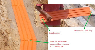
However, another alternative appeared a few years ago in a form orange-colored, thin interlocking PVC plates.

This method has been used in most projects that I handle nowadays and is shown in the following picture.

Picture 05 – A worker placing PVC protective covers over the sand cover

(Click on the picture to enlarge it)

Each piece of the PVC plates is embossed (not printed) with suitable DANGER warnings. The printed warning types are still available today, but I always insist on the embossed types because a low quality printed warning can get eroded over time, or due to improper handling during installation.

Picture 06 – PVC protective covers

(Click on the picture to enlarge it)

After the placement of the protective PVC covers, the cable trench is backfilled with good earth and compacted every 6 inch until the finished ground level.

It is also a good practice to top the earth up by about 2 inch above the existing level to allow for settlement of the newly backfilled cable trench.

Often the civil work contractor would continue with the ground finishing work or the road work after the electrical contractor has completed the underground cables installation. They may not insist on the two inch top up.

However, the compaction of the sand layers and the earth backfilling are always an issue between the electrical contractor and the civil or the main contractor of a project. Therefore it is always wise to stick to the requirements of the contract as the minimum.

Many times even the specifications of the contract are not tight enough which leads to disputes between contractors after the cable laying has been completed.

Worse still if the dispute appears just before the handover of the newly completed building to the owner, or just after the commissioning and operation of the building, when some settlement on the finished ground or the finished road begin to appear.

To say it simply, this is one of those areas where a wise judgement on the part of the supervising engineers is needed.


Copyright http://electricalinstallationwiringpicture.blogspot.com/ Underground street light cables