Tuesday, March 30, 2010

MATV antenna bracket pictures

I have a few installation pictures of MATV antenna brackets. In fact I have quite a number of pictures on the installation of other building services such as the public address system, the firemen intercom, audio visual and conference system, etc.

=================  RELATED ARTICLES: MATV trunking riser  |  Lighting flexible conduitsA simple electrical installation | Electrical socket extension unit  | 1- Phase ELCB connection pictures  | Bare fluorescent light pictures  | Recessed down lights installation  | Bollard light pictures  | Light switch installation pictures  | Home wiring pictures  | Electric Meters  | Electrical Grounding Electrode Pictures  | Most Basic Principles of House Wiring |
=================

All these are part of the electrical contracts in a building construction works.

They are classified as building services together with the cold water supply, the fire protection sprinklers, etc.

When I started this blog, I wanted to make it specialized in only electric supply systems.

However, I have also always asked myself what to do with all the pictures on the ELV (extra low voltage) systems and telephone works.

It has been such a waste. Those pictures can be of use to many people such as those whose need real installation pictures of the systems in real construction works.

Even I myself was having such needs during my early days in the electrical world. Of course, now anyone can search among the tens of thousands of the manufactures’ and suppliers’ websites specialized in these systems.

However, often we only find nice pictures and often we do not want nice pictures.

We want the real construction pictures, pictures that are not biased towards any particular supplier or manufacturer.

For this reason, I am expanding the scope of this blog to also include the installation pictures of building’s extra low voltage (ELV) services and telecommunication systems.

In the future, I may even include building’s ICT systems.

After all, the title of this blog is “… installation pictures”. The internet search engines should not be confused about the content of this blog, I think. We will see.

Now let’s get back to the pictures.

I will not be writing much on this. My specialty is not on these technologies. I only have some experience with them, including design (aka system integrator) and installation supervision.

Therefore, I will only be going through the pictures very briefly when it comes to the ELV services and telecommunication systems.

Picture 1 – Installation of MATV antennas


I apologize if you need to look closely at the picture to see the antennas. I should have taken the photographs before they started work on the roof installation. The green color of the construction safety nets seems to have disturbed the clarity of the antenna image in the picture.

However, Picture 2 below shows the antenna brackets quite clearly.

Picture 2 – Antenna brackets mounted to a roof wall


Well, there is nothing special with the brackets here. Just similar to the types that you may have at home.

However, observe that stay wires were used to add stability to the poles. You may not have the stay wires at home.

Picture 3 – Closer view of a bracket


Picture 4 – The flexible conduit connection between cable trunking and the rigid steel conduit


Below is an example single line diagram for an MATV installation at a multi storey building. I hope it will help “genuine” beginners place where the antennas are located in the overall system of the MATV installation.

It was part of a draft proposal for a turnkey project many years ago. So it is simple enough and easy to understand.

It was also the first AutoCAD soft copy file that I found in my old archive when I started digging for a schematic diagram to complement the above MATV pictures. I would not want any beginner reader to leave this post confused.

A list of the symbols used in the diagram also follows.

Observe and try to understand. I am not a teacher here. I just share pictures with you.

Diagram 5 – MATV single line schematic diagram for a multi storey building


Diagram 6 – TV antenna symbol


Diagram 7 – Satellite TV antenna symbol


Diagram 8 – Lightning arrestor symbol


Diagram 9 – Amplifier power supply symbol


Diagram 10 – Channeled amplifier symbol


Diagram 11 – Final amplifier symbol


Diagram 12 – 2 way tap off symbol


Diagram 13 – 4 way splitter symbol


Diagram 14 - 2 way splitter symbol


Okay, guys. Enjoy the photos.

Visit also this post, Electrical installation pictures, to see more photos on this blog.


Copyright http://electricalinstallationwiringpicture.blogspot.com MATV antenna bracket pictures

Sunday, March 28, 2010

Compound Lighting Installation Pictures

You will find below some pictures and diagrams on the installation of compound lighting. Only one type of lighting you will see today. I will upload other types some other day.

Picture 1 – Compound lighting installation


================ RELATED ARTICLES:  Electric Cable Drum Pictures | Underground street light cablesCompound lighting storage yard | Feeder pillar single line diagram | Bollard light pictures | Feeder pillar hazard pictures  | Compound lighting foundation size  | Electrical installation pictures | Architectural Lighting
================

The construction at the above site was still in progress when I took the above picture.

The woodwork that you see around the light pole in the picture was for the landscape work. The project was in the final phase of construction.

The external lighting and landscape works were progressing in full speed.

The underground cabling for the compound lighting has been installed. The electrical contractor was then progressing with the installation of the foundation for the light poles.

The light pole in Picture 1 was installed as a mock-up unit so I could check and comment. I took some pictures at the base of the pole for reference, which you can see below.

I however rejected the mock-up unit because the internal wiring and termination was not yet carried out.

When the wiring is done, I will take some pictures and send them up here for readers who need them.

Picture 2 – Light pole mounting base


Some readers may say that this is a strange way to locate a light pole, which is above the drain. A more normal method would be more or less like the one in Picture 7.

Here the design-and-build contractor had a problem of locating a few of the compound the light poles at the open carpark area because there are several drains running between carpark boxes.

These drains were supposed to be located at the boundary of the land being developed.

However, it turned out that with the presence of the drains the actual land space for the landscaping works (e.g. trees, shrubs, etc) was too narrow to grow larger trees.

Therefore, the client agreed that the drains be relocated through the middle of the carpark area.

Construction people tend think that electrical things are very flexible and easy to be moved around just like a wiring cable.

I never liked that notion. It is true in this case, however.

Now the compound light poles have clashed with the drain. At some places, the poles have been moved to between two carpark boxes.

However, there have been concerns that accidents may damage the light poles.

As a result some poles of the compound light were located right above the drains.

The main contractor asked me how to place the pole bases on top of the drain cover.

I told them that the only real solution I have ever seen in such situations was only by constructing a cast in concrete base together with the drain, with the construction drawings of the light pole’s concrete foundation designed and endorsed by the civil work’s design consultant.

Anything less would be an experiment and I would not accept anything less because the building under construction was a high profile building and an important landmark.

A failed method of installation of the compound light poles would be extremely embarrassing for the supervising engineer, which was me.

The building owner’s resident project manager was aware of the problem and this helped me get a reliable concrete foundation for the 8 meter steel poles of the compound lighting.

Picture 3 and 4 below shows the concrete base work is progress. Observe the reinforcement steel bars used.

The completed base is what you see in Picture 2 above.

Picture 3 – Construction of a light pole foundation on top of a drain


Picture 4 – Another view of the light pole base


Picture 5 below gives another view to show the mounting bolts and nut above and below the pole’s base plate.

Picture 5 – Another view of the pole’s base plate mounting


Picture 6 – Another pole base just completed


Picture 7 – A precast light pole foundation in position


Another cast in situ pole base. I show this picture just to show the readers the entry method of the multi-core underground cable.

You can see two lengths of cables because this pole would be in the middle of the loop circuit along that light row.

If you do not understand this, leave it. I will explain the circuit in detail in future posts. With some picture too.

That was the more difficult part of the compound lighting installation in this project.
This type of electrical installations is usually simple works. Not much difficult issues.

I have more pictures on the compound lighting that I wish to upload to this blog. I am however too tired already. It’s already 4 am.

I will upload the other pictures in future posts.
Chiao.


Copyright http://electricalinstallationwiringpicture.blogspot.com Compound Lighting Installation Pictures

Electric trunking installation pictures

As will be shown by the pictures below, no electrical installation work of a significant size can be done properly without the use of an electric trunking.

A trunking is a larger size of a conduit. When you need to run a number of electric conduits along each other for a significant distance, then consider using a trunking in place of the conduits. There are so many sizes you can choose from.

Picture 1 – Electric trunking running below soffit of floor concrete slab


=================  RELATED ARTICLES: Underfloor trunking below structural rebars |  Lighting flexible conduitsConduit to trunking connections |  Cable ladder picturesElectrical conduits and trunking picturesElectrical panel under water pipes  | Electrical busduct installation pictures | Electric conduit installation pictures    | Electric Panel Installation Pictures  | FR electric cable installation pictures  | Multi storey building electric closets  | Underfloor trunking pictures  | Site-fabricated electrical trunking  | Electrical Services Color Codes  | Light switch installation pictures | Electrical installation pictures
=================

This is an example of a trunking installation above ceiling level, under the soffit of the concrete floor slab.

I also labeled some of the other services there for the benefit of those non-electrical readers who need pictures like this for reference, to know what is what among the myriads of pipes and wires running above the ceiling level.

Notice the label “E” and “N” on the electric trunking. “E” means Essential Supply and “N” Normal Supply.

All large buildings need labels of some sort to distinguish two types of electric supply: the “normal” electricity supply and “essential” electricity supply.

The normal supply means the supply that is obtained from the public electricity supply. When the public supply fails, then your have a black-out.

If you live at a higher floor of a flat building, then you have to walk down the emergency staircase to leave the building.

That is why an “essential” supply is provided. This is normally generated by one of more standby diesel generators.

When the public supply fails, the standby generator automatically kicks in and provides the electricity to the building through the cables run inside the “E” trunking.

If you wall socket is supplied from these cable, then you have electricity even during a black out.

Picture 2 below shows how the electric trunking is installed at location like this.

Picture 2 – Hanger rod


Two hanger rods and a length of angle iron are normally used to support the trunking at these types of location. The angle iron can be as long as is necessary to accommodate the number of trunking it will support.

The hanger rods would be as long as needed to position the height of the trunking to a level that would necessitate a minimum number of bends.

Bends are more expensive than the straight piece regardless of whether you buy it ready made from factory or fabricated at the site from a straight piece.

Custom made at site means labor costs, which can even result in a much higher cost in the end.

So far all the clients of the projects that I was involved in did not accept custom made trunking bends. Neither do I.

Custom made bends tend to have sharp edges that injures the insulation and protective outer sheath of electric cables.

Injured cables can cause many problems during the operation of the installation even though they normally seem to pass all tests and inspection during construction.

I always warn contractors not to use custom made trunking or cable tray bends. When they have to, they are required to notify me or my staff in advance and specific locations where they are used should be identified and permission granted for each one on case by case basis.

Picture 3 – Vertically mounted trunking


This picture shows electric trunking when they are mounted vertically.

This installation was inside a fan room at the roof of a multi storey building. A number of electrical panels would be located on that wall later. That is the reason for the multiple trunking installed.

This room was basically a machine room. It housed many of the smoke control and ventilation fans of the building.

As usual, wiring to machines and electrical equipment requires frequent maintenance due to overheated cables, addition of new machines, replacement or upgrading to bigger machines, etc.

All these reasons require frequent troubleshooting and rewiring of electric cables. The use of trunking makes the maintenance and upgrading work much easier. That is why trunking are used in these sorts of locations even though there would only be just a few small electric cables to be installed inside them.

The following pictures show how the trunking are fixed to the wall, the types of mounting brackets used, etc.

Picture 4 – Mounting bracket for wall mounted trunking


The above picture and the one below show two types of mounting brackets. These two are the low cost types.

Picture 5 – Another type of vertical mounting bracket


Same method, only different materials.

The type shown in Picture 6 would cost more, but it can provided higher strength which is needed for long vertical trunking such as those inside electrical risers in a multi storey buildings.

Picture 6 – Mounting bracket for long vertical trunking


This type also is suitable for large trunking sizes, which can carry more cables.

Picture 7 – Trunking 90 degree bend


This is an example of a bend. This one was factory-manufactured.

Picture 8 – A hanger rod support bracket installed by the air-conditioning contractor


This trunking and the hanger rod support were installed by the air-conditioning contractor. It is exactly the same as the method used in Picture 2.

However, I show this picture for a different reason.

Notice the white label “AC” painted under the trunking. This label is painted to all electric trunking installed by the air-conditioning contractor to distinguish them from electrical trunking installed by the electrical contractor.

It is a common practice that all electrical conduit and trunking are required to be painted orange color.

An air conditioning system runs throughout all floors of a modern high rise building. The locations of air-conditioning electrical equipment are not restricted to just inside the AHU rooms of a building floor.

There are numerous fan coil unit (FCU) throughout the floor area. Where individual control of the air temperature and quality inside a room is required, an FCU unit is needed.

So, an electric circuit need too be run there.

Many times, especially in large buildings, the works of electrical wiring to all these air-conditioning electrical equipment are located inside the air-conditioning works contract.

If for nothing else, this arrangement eliminates many coordination problems that usually occur when too much interfacing is required between different trade contractors.

The electrical contractor is then just required to run supply cable to the main electrical panel of the air-conditioning system at each floor. The electrical panel and all downstream cabling and wiring are parked under the air-conditioning contract.

Neat.

Okay. This is all I have time for today. We will meet again in the next post.

Readers new to this blog can find more pictures by visiting this post, Electrical installation pictures. There you will find links to other posts that contain pictures on the topics that you are looking for.

That is faster than searching in the ARCHIVE sidebar.


Copyright http://electricalinstallationwiringpicture.blogspot.com Electric trunking installation pictures

Saturday, March 27, 2010

Electric Panel Installation Pictures

The two pictures below show two electric panels that I took while the installation was in progress. The small panel on the far right is actually the telephone DP.

Picture 1 – Electric panel installation for a typical floor at a high-rise office building


=================
RELATED ARTICLES: Conduit to trunking connections |  Cable ladder picturesElectrical conduits and trunking picturesElectrical panel under water pipes  | Electrical busduct installation pictures | Electric conduit installation pictures  | Electric trunking installation pictures    | FR electric cable installation pictures  | Multi storey building electric closets  | Underfloor trunking pictures  | Site-fabricated electrical trunking  | Electrical Services Color Codes  | Light switch installation pictures | Electrical installation pictures
=================

Picture 2 – The front view of the electrical panels


Why would I want to show the readers these pictures?

There was something wrong with this panel installation. The telephone DP is not a problem, but the installation of the electrical panels was not acceptable.

The high-rise building electrical system

This building was a high-rise office building. At every floor there were a number of electrical panels to serve all the lighting and power requirements on that floor including the lighting, switched socket outlets, toilet exhaust fans etc, etc.

Some areas of the office used an open floor office systems so under floor trunking was also used here.

A few of the panel were located inside the riser room of each floor. However, since each was a large area some panels needed to be located at the office area. Wiring directly from the electrical riser would be unnecessarily too long.

Therefore, the electrical consultant locates these electrical panels along the corridors throughout the building. The design architect was requested to provide small rooms to house the panel.

Alternatively, small electrical cabinets with lockable doors and sufficient work access and ventilation would be acceptable.

The Client-Consultant Meeting

Four months before I took these pictures, during a weekly site coordination meeting, the design architect asked me if they could just house the electrical panels inside cabinets but the doors would not be provided with locks and keys.

You see, this was a design-and-build contract.

In a design-and-build contract, the main contractor employed all consultants. So all design consultants were obliged by contract to assist the main contractor in any effort to optimize the design (to save more money actually).

They call this “value engineering”.

I was the site supervision engineer on behalf of the electrical design consultant in this project.

Okay, back to the meeting I mentioned earlier. The design architect asked me if they could just house all the electrical panel in the office areas in small cabinets but the doors would not be provided with locks.

They had no budget for the locks. The design architect said he did not know they needed to lock the electric panels.

If locks were provided, the main contractor might decide to deduct the consultant’s design fees to cover the cost of the locks. “The consultants should be responsible for any omission from the design”. Those were the words.

I said NO.

The discussion and arguments about this matter went on for more than half hour.

I maintained my position that the electrical panels should be housed in enclosures with lockable doors and access provided to all the electrical trunking in and out of the panels.

The basis of my position was that all those panels were designed to be housed in side a protected enclosure. That was why all panel doors were not provided with locks.

I defended my position and in the end the architect and the main contractor’s project manager gave in. I won.

The Value Engineering trick

However, supervising a construction work under a design-and-build or turnkey contract was never easy.

The main contractor is not afraid of the consultants, or the resident engineers, which are the consultants’ representatives at site.

Four month after that meeting, the contractor’s M & E Manager told me they have made a mock-up of the electric panel enclosures and they wanted me to check and see if it was acceptable.

I went to see the mock-up with the M & E Manager.

Surprise! You can forget about the locks and the keys. The electrical DB’s were not even housed in a cabinet, let alone a DB room or something.

I told him that I rejected the mock-up and took a few pictures (Picture 1 and 2).

He argued that they do not have enough time because the building must be handed over to the owner in six weeks, failing which there would be LAD imposed to the main contractor by the building owner.

A few days after, one after another of the main contractor’s site people came to see me and asked me to approve the mock-up enclosure for the panels.

Now a new round of arguments came up. I maintained my position, of course.

In the end, which was the next day, the Project manager told me they would proceed to comply with my requirements but I needed to submit to them the codes that were the basis of my position.

IEE Wiring Regulation Sixteenth Edition 1991

I was not in the mood to write any Site Memo, so I just went out and took the IEE Wiring Regulation Sixteenth Edition from my car.

I photocopied Page 25 and Page 30.

Page 25 was the content page for Chapter 41: Protection Against Electric Shock, while Page 30 contained the detailed regulations relevant to the issue at hand, which were: (a) Regulation 412-03 - Protection by barriers or enclosures; (b) Regulation 412-04 – Protection by obstacles; and (c) Regulation 412-05 – Protection by placing out of reach.

At the Regulation 412-03-01, I highlighted with yellow markers the words “… Live parts shall be inside enclosures or behind barriers…” and jotted down the following hand written comments:

“The instruments installed at the front of the panel are fragile and they have not been designed for toughness. Any accidental damage to these instruments may expose the internal wiring and other LIVE parts.”

At Regulation 412-03-04 (i), I highlighted the words “ … the removal or opening shall be possible only by use of a key or tool.” And gave the following comments:

“The inside of the electrical DB’s should only be accessible by use of a key or a special tool.”

I initialed both hand-written sidebar comments and put down my Resident Engineer rubber stamp.

The main contractor's Project manager received the original copy later in the day.

The following Monday I saw the furniture subcontractor commencing works to modify the electrical DB enclosure.

Check out the photographs below to see the components that were mounted at the front panels of the electrical DB’s. I also gave a few lines of comments on the functions of the instruments for the benefits of casual readers. This blog is intended for beginners mostly.

Picture 3 – The DB voltmeter


This instrument measures the voltage of the incoming electricity supply. The two DB’s here are three phase DB but one voltage meter is provided. So, only one voltage can be read.

That is why a SELECTOR SWITCH is always provided (see Picture 4 below). You can change which voltage of the three phases (Red, Yellow or Blue phase) to read.

However, there six voltage positions there.

For the real beginners: The reason there are six voltages is because not only there are three phase circuits that you can connect you appliances to, but there are three other which are Red-to-Yellow, Yellow-to-Blue and Blue-to-Red. These phase-to-phase voltages provide 415 volt each, while the single phase (either Red, yellow or blue phase) only give 240 volts.

If you have a large steel gate at your house entrance and it is motorized, then it is probably using the 415 volt. The normal 13A switch socket outlet that you connect your washing machine to is a 240 volt supply.

Picture 4 – The voltmeter SELECTOR SWITCH


There is an OFF position, which means you would not read any voltage at this position. That is why the voltmeter in Picture 3 reads “zero” volts. The voltmeter switch is in the OFF position.

The transparent front plate of the instrument is actually made of some plastic material, and it can easily be broken by accidents.

Picture 5 – The ammeter (current meter, or Ampere Meter)


This is similar to the voltmeter except that it reads the phase currents. A selector switch is also provided (see Picture 6) to select which phase current the meter would show.

Picture 6 – The ammeter selector switch


Picture 7 – The phase indicating lights


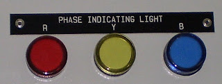
When these lights are ON, then you know there is electricity in the electrical panel. It tells in a quick glance, from far away.

In most electrical panels, these light are connected the circuit before DB main circuit breaker.

That means if you open up the electric panel and turn OFF the main incoming circuit breaker, these lights would still be ON.

Why would we want it that way?

Because there is still electric supply in the DB and therefore it is still deadly dangerous.

You can only make the lights OFF by switching off the circuit breaker (or fuse) at the source supplying the DB.

This is an important life and death matter.

Picture 8 – Panel door screws


This the screw used to secure the door. There are two screws for each electric panel door in the picture, at the top and bottom of the door right side.

You would not need any screwdriver or other tool to turn these screws and open the electric panels. In fact, they are designed to be opened easily with the two fingers.

So anybody can open them. Do not get me wrong. There is nothing wrong with this design. It is one of the most widely used practices in electric panel design if they are intended to be housed in a protected room or cubicle.

If the designer intends to locate the panel at areas accessible to public, a lockable door with key would have been specified.

Alternatively, they can be located at a position reasonable out of reach. At some height, for example.

Picture 9 – 
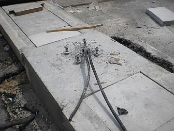
Electrical trunking in and out of the electric panels


There are electrical trunking connecting the panels in Picture 1 and 2 at above and below the panels. But the box-up walls have hid them. Picture 9 show example of one of these metal trunking.

In future, the maintenance electrician would need to access and open the cover of the trunking in the repair and upgrading works. Therefore, a means of access is required, which was not provided at all at the mock-up unit.

That is all the time I have for this blog today. Visit this post, Electrical installation pictures, to see pictures of electrical installations.

(Update April 2010: The electrical panel box-up has been rectified. You can see the pictures at this post, Multi storey building electric closets.)

Visit the following post if you wish to see pictures of electrical injuries. However, first make sure you really want to see them. Some people do not like to see pictures of serious accidents. The pictures are here: Electric shock injury pictures


Copyright http://electricalinstallationwiringpicture.blogspot.com Electric Panel Installation Pictures

Thursday, March 18, 2010

Substation main earth bar pictures

You will find below a few pictures of HV electrical substation’s main earth bar. I took these pictures inside a Consumer HV room at one of my recent building projects.

Picture 1 – Location of the main earthing bar inside a HV Switchgear Room


Observe the location and position of the main earth bar in the HV room. At every electrical room of significant size, at least one main earth bar like this should be provided.

Picture 2 below shows a closer view of this earth bar.

=================
RELATED ARTICLES:
Exothermic welding: Cable to cable connectionsElectrical grounding  | Electrical Grounding Electrode Pictures  | Switchboard earthing picturesLightning roof conductor installationLightning Earth Rods Installation | Temporary Electrical Earthing Pictures | Electrical installation pictures
=================

Picture 2 – HV Room’s main earth bar


The purpose of having the main bar is simple.

All earthing conductors inside the HV room would be connected to this bar. That is the reason you can see in Picture 2 a number of ready-made termination holes complete with bolts, nuts and spring washers.

Notice the main copper earthing tape mounted along the substation wall in Picture 1. This is the main equipotential earthing conductor for this electrical room.

It should run through all perimeter walls of the room at a height of approximately 12 inch from the substation’s finish floor level. That is why you can see that in Picture 2 the left-most and right-most terminals have been connected with a horizontal copper tape conductor.

An ideal installation would have the main equipotential conductor run in a ring around the perimeter walls and both conductor ends connects to the main earth bar at the left-most and right-most terminals.

However, in this case it was not in a ring at the time this picture was taken because there was an entrance door at the wall in front of the 11 KV switchgear. Picture 1 was taken at the rear.

Later the horizontal copper tapes were connected into a ring by running additional conductor above the entrance door.

What are the conductors connected to the main earth bar in Picture 2?

The horizontal tapes at the left and right are what I have explained above.

The other three conductors have been installed vertically down into the cable trench.

(NOTE: Notice that the cable trench has been filled with river sand. Many installations prefer to have cable trenches filled with sand to avoid problems with rates and snakes playing hide and seek inside the cable trench.

Once a while these live beings find their way into the electrical switchgears and cause many problems including short circuits and intermittent trippings.

I have come across many operational problems because of these reasons.

To overcome these problems, many operation engineers prefer to just have all substation cable trenches filled with river sand. Then the trench is finished with approximately one inch of lean concrete on top of the sand and level with the substation floor.

When they need to do some work in the trench, they just knock down and break the thin concrete and dig out the sand.

No doubt this is a messy way of doing things, but it seemed to have been a very practical solution to these sorts of problems.)

Back to the earth tapes run vertical down into the cable trench. Where are these tape conductors for?

From the right, the first vertical conductor is connected to the HV switchgear equipotential conductors.

The center vertical conductor is connected to the earth busbar inside the switchgear compartments.

The last vertical conductor, at the far left, is the connection to the earthing electrodes outside the HV room.

Picture 3 – Disconnecting earth terminals


Some of the readers may not notice that the earth bar in Picture 2 is actually a two-piece bar. The two separate pieces are much more visible in Picture 3 above.

Notice that there is just one terminal (other than the terminal for connecting the two bars) on the short piece, while there are six terminals on the longer bar.

This has been designed to be so. The terminal on the short bar is called “disconnecting terminal”. The whole assembly is purchased readily assembled by manufacturer.

Usually earth bar with one or two disconnecting terminals are readily available. If an electrical contractor needs more disconnecting terminals, then it need to be ordered and it would be fabricated as required by the project at hand.

The terminals on the shorter piece are intended for testing and trouble-shooting purposes. That is why the conductor to the grounding electrodes is often connected to the short piece.

However, so clients forbid the use of the disconnecting terminals altogether. These sorts of clients usually manage many separate electrical installations with separate local operation teams.

It is usually not always easy to ensure an adequate level of competency of each member of the local operation and maintenance teams.

An earth lead conductor connected to the disconnecting terminal may easily lead to a total absence of connection to the earth electrode.

This presents a very serious safety risk.

This lead to a policy of forbidding the use of the disconnecting terminals. Therefore, all their substations would have single-piece earth bars.

Picture 4 – HV switchgear body earth conductor


This photo gives a clearer view of the switchgear equipotential bonding conductor.

As you may be aware, the switchgear came in separate smaller panels and the individual panels are then connected and bolted together at site.

The switchgear body earth (another name for the enclosure equipotential bonding) conductors, as indicated in Picture 4, have also been installed and bolted to each individual panel.

Therefore, these individual lengths of body earth conductors are connected and bolted to each other at the construction site.

The short inter-connecting copper pieces and all accessories including bolt-and-nuts for making the complete connection are provided by the switchgear manufacturer and shipped together with the rest of the panels.

Picture 5 – Bolt, nut and spring washer


This may be obvious for most readers, but some beginners may be silently screaming for help. So I labeled these components for them since they are such critical components in the electrical grounding system.

Picture 6 – Earth bar insulator post


Copyright http://electricalinstallationwiringpicture.blogspot.com Substation main earth bar pictures

Wednesday, March 17, 2010

Electric conduit installation pictures

You will find a number of installation pictures of electrical conduit in this post. I will not be writing much today, so this post will only present pictures.

Picture 1 – Surface run conduit


=================  RELATED ARTICLES: Underfloor trunking below structural rebarsMATV trunking riser |  Lighting flexible conduitsConduit to trunking connections |  Cable ladder picturesElectrical conduits and trunking picturesElectrical panel under water pipes  | Electrical busduct installation pictures   | Electric trunking installation pictures  | Electric Panel Installation Pictures  | FR electric cable installation pictures  | Multi storey building electric closets  | Underfloor trunking pictures  | Site-fabricated electrical trunking  | Electrical Services Color Codes  | Light switch installation pictures | Electrical installation pictures

===========

What you see here are surface run conduits inside a fan room of an office building.

For some reason that I do not know, personally I like surface run conduits, trunking, etc.

I also like to see things exposed like the exposed structural elements of a covered stadium.

Being able to see the things myself make me feel comfortable.

In the case of these conduits, having them exposed on the wall like that leave no room for any contractor to play with their tricks.

There is no doubt that concealed conduit works help keep the electrical system away from interference and possible accidental damage.

This is important where the space is a public space like a public corridor of a building.

Residential buildings are also not a good place to use surface run conduits like shown in the picture, even though surface run wiring (without conduit) used to be a standard practice in house wiring.

Why do we need these conduits?

The conduits are used to protect the wiring cables that carry the electrical current.

Electricity is dangerous. Even though the electric conductors that carry the current is insulated by some PVC covering materials or whatever, the covering material is not strong enough to protect the cable from damage.

When the covering is damaged, the electrical conductor inside may be exposed to touch or it can also unintentionally come into contact with things that can carry electric current.

This scenario would present a high risk of electric shocks.

Therefore, we protect the electric cables so that they do not present the dangers of electric shocks to people (or animals).

A second reason to protect the cables is to make sure the electrical system stays reliable.

When the cable PVC covering is damaged, the conducting metal can come into contact with other metals that are in contact with earth.

When this happens, the leakage protection of the electrical system will automatically trip the circuit breaker controlling the circuit whose cable has been damaged.

Damaged electric wiring cables can cause this tripping at time we need the electricity most.

Therefore, electric conduits are used to provide this reliability.

Picture 2 – Conduit connection to light switch concealed box


This picture shows how the electrical conduits are connected to the metal boxes.

These boxes are installed to house the rear of wall-mounted light switches. A 13A switched socket outlet mounted flushed to a wall would also have this concealed metal box.

The purpose of the box is to provide a protected space for the wiring cables from the conduit. This space gives enough room for the cables to maneuvers before terminating at the light switch or the socket outlet.

The space also provides the room for the rear portion of a switch unit to sit in.

With this method, we can change a switch unit when it is damaged without disturbing the wiring system too much.

Note the four screw holes already provided by the metal box.

Now, when the electric conduit is cut to suit height of the box, there may be sharp edges at the conduit end. These edges may damage the PVC insulation covering of our wiring cables.

A careful workmanship can easily trim the sharp edges, but controlling workmanship is not easy.

That is why a copper bushing is provided as you can see in the picture.

The bushing also helps to give good contact between the metal box and the metal conduit.

Did I forget to say that these conduits are made of metal?

They are actually galvanized steel conduit.

You can use the cheaper PVC conduit for the same purpose if you like. In that case, you may still use a suitable PVC bushing but not for the purpose of providing e good electrical contact.

The conduit in picture 2 is a concealed conduit for a dry wall partition. So the metal box is a concealed box.

Picture 2Picture 2a below show connection of sufrace conduit to a supface mounted switched socket outlet. The same method of conduit to metal box connection is required here except that the metal box is exposed so it it is a different design.

Picture 2a - Conduit connection to surface mounted 13A switched socket outlet


Picture 3 – Conduit saddle picture


When a conduit is installed exposed like those in Picture 1, it may sag if the distance between two supports exceed certain distance.

An electrical conduit must be installed rigid, permanent and without sag. It should also be able last with integrity for the design life of the building.

What if the building can last 100 years? Should the conduit installation be able to last 100 years also?

Well, if it can, then that is good. However, a wiring system will not be good enough 50 years from the time the building is constructed.

Technology change, how people use electricity change, the personal taste and preference of the people occupying a building space also change. All this will result in the need to renovate the building, and most likely the wiring system also.

The conduit system would not need to last 100 years.

However, it should be able to last 30 years. This is my opinion.

Therefore, once installed, the electric conduit should be rigid, permanent and strong.

In order to satisfy that, electrical installation specifications usually specify the maximum distance between conduit saddles. Some say 900 mm, some say 1100 mm.

The size of the conduit, the materials and the installation environment also are among the major factor in determining the maximum distance between the support saddles that is allowed.

The distance for the orange electrical conduit (the red painted conduit carried fire protection system wiring, not electrical cables) in Picture 1 is around 1.1 meters.

I am guessing only here.

I did not really check the distance. It looked reasonable when I was supervising the job. However, the specifications asked for 900 mm maximum for a one inch diameter conduit, if I remember correctly.

Do not quote me on this. If you are supervising a job, check your own specifications.

If you are doing your office wiring on your own, just keep the saddle spacing to 1000 mm.

Picture 4 – Draw in box


Some people call this a junction box; draw in box, or outlet box.

Whichever name you prefer, this component allows the electrician to draw in cable into the conduit a short length at a time.

If one tries to pull wiring cable into a conduit for too much distance in a single shot, he may find it very difficult to get the job done.

In real installations, the routes available for conduit installation are not straight all the time. There are bends and turns. These bend and turns plus the cable friction with the conduit interior make it hard to pull the wiring cables.

Forcing it too much may damage the cables permanently.

By practice, a maximum of 9 meter distance between draw in boxes on straight run conduit has proved to be practical enough for most wiring works.

If there are bends, then the box should be installed after every two bends.

Okay folks. That is all the time I can spare today.

See you in the next post.

P/S : You can see more pictures at this post, Electrical installation pictures.


Copyright http://electricalinstallationwiringpicture.blogspot.com Electric conduit installation pictures

Monday, March 15, 2010

Electrical busduct installation pictures

The following pictures show electrical busduct risers in actual installation.

Picture 1 – Typical busduct rising main at individual building floors


================= RELATED ARTICLES: Underfloor trunking below structural rebars |  MATV trunking riserSubstation rooms layout diagram |  Conduit to trunking connectionsCable ladder picturesElectrical conduits and trunking picturesElectrical panel under water pipes   | Electric conduit installation pictures  | Electric trunking installation pictures  | Electric Panel Installation Pictures  | FR electric cable installation pictures  | Multi storey building electric closets  | Underfloor trunking pictures  | Site-fabricated electrical trunking  | Electrical Services Color Codes  | Light switch installation pictures | Electrical installation pictures | Building’s electrical rooms layout

=================

The above picture shows a typical installation of busduct rising mains in the riser room at individual floor of a high rise building.

This picture was taken in the riser room at one of the upper floors of a high rise building.

From the picture you can see most of the major components of a busduct riser system.

(NOTE: for readers who are not from electrical disciplines, a “riser” is a feeding cable or pipe giving supply to upper floors of a multi-storey building.

In electrical works, a riser is a set of cables the supply the upper floors. The electrical distribution diagram in Diagram 3 may make you understand this better.

The feeding cables “rise” up straight to the top floor. Then at each floor a tap-off unit is connected so electricity can be supplied to that floor.

An alternative is to run one individual set of cables to each floor. Then there would be many cables that need to be installed the number of which is directly proportional to the number of upper floors.

One single set of bigger cables is always cheaper to install and much easier to handle.)

Observe that there are three tap off units there: two units of 60A three phase, and one unit of 100A three phase. The one at the highest position of the three is the 100A tap off.

Why three units?

There are actually three risers here: one for the “normal” main electricity supply. This supply is just the normal authority supply like the one you have in your house. The 100A tap off unit is for this riser.

The second tap off, which is one of the 60A units, is what is called “essential supply”, or “emergency supply”. It is a normal authority supply like the one you have from the 100A tap off unit above.

However, it is also backed by a standby diesel generator. This means that if the electricity supply from the authority distribution network fails due to problem with their underground distribution cables or whatever, the standby electric generator would kick in and switch in the locally generated electricity to this electrical riser.

Large capacity electric generators are expensive, however.

Therefore, it is not economical to supply all electricity needs in the building from this generator. That is why separate electrical risers are used, and the “normal” riser is not backed by the generator supply.

The third tap off unit (the second 60A unit) is for the air conditioning system.

It is quite common (and is considered a better design) to have a separate feeder cable for the air conditioning and mechanical ventilation (ACMV) system in a large building. That is the reason for the third electrical riser here.

One more point to note here is that some office buildings use the generator-backed supply (i.e. ESSENTIAL supply) to feed the electrical riser for the air-conditioning system.

With this arrangement, ACMV equipment that need to continue operating even during the mains failure do not need to be connected to “ESSENTIAL” supply riser, which is why it is given a separate riser in the first place.

Observe the large flexible conduits coming out from the bottom of the tap off units and connect to the orange-colored electrical trunking. Some installations use rigid metal trunking for this purpose.

Cables are run from a tap off unit into the flexible conduit to go to the orange metal trunking.

They run inside the trunking to connect to the respective sub-switchboard.

You can see only two sub-switchboards here. These are for the “NORMAL” supply and the “ESSENTIAL” supply.

The switchboard for the air conditioning system is normally located inside the AHU room of that particular floor.

From the sub-switchboards, separate outgoing cables are run inside the trunking to connect to separate distribution boards (DB) on that particular floor.

That is all that I wish to elaborate on Picture 1 above.

My intention is so that beginners in electrical installations can understand the major components that make up a busduct riser system.

Now let us look at a few electrical diagrams. The diagrams can give a more complete overall view of a simple electrical system in which a similar busduct riser forms a part.

While the busduct risers in Picture 1 are for a high rise office building, the following diagrams are for much simpler installations. They are for the nurses hostels at a hospital complex.

Even though electrical installations at hospitals are relatively much more complex than the office building above, the installation at their hostel and staff quarters buildings are usually very simple.

That is why I choose to use them here. My objective here is to give casual readers and beginners in electrical works an overview and general understanding of the basic functions and installation of a busduct riser system.

The actual electrical diagram used to construct the installation in Picture 1 might be too complicated for this category of readers. I do not wish to scare them away.

Diagram 2 – Part single line diagram for a multi-storey nurses hostel


This diagram is part of a larger diagram which is in Diagram 3.

Diagram 3 – The full layout of the single-line of Diagram 2


As you can see, you cannot read much of the labels and notes in Diagram 3.

I produced this JPEG graphic from an AutoCAD drawing files (i.e. DWG file format) which is probably the most widely used drawing programs in the construction industry.

I used the program’s BMPOUT command to produce a BMP file format form the DWG file format. Then I converted the BMP format into the JPEG file format using the Microsoft Paint program.

However, this method does not seem to be effective enough for AutoCAD drawings that have been produced for A1 or A0 printing as the original sizes.

If anybody here knows a better method, please let me know.

Okay. Let’s get back to the electrical single-line diagrams.

In Diagram 1, you can see that the hostel building is six-storey, which Ground Floor, then Level 1 to Level 5.

Usually for a building of this height, designers do not use busducts. However, they do in this case. Maybe that was because the project already used so many busducts at the main hospital complex and other (much higher) staff quarters buildings, it made sense to also use busducts here.

In any case, the components of the busduct system that you see in Picture 1 were used at each floor of Level 1 to Level 5.

However, at Level 1 you have one or two more components. Picture 4 below shows a view of the electrical riser room at Level 1 (the first higher level). It is the same building as that in Picture 1.

Picture 4 – A view of the electrical riser room at Level 1 (the first level above ground level


As you can see, there are definitely more components here that in Picture 1.

However, actually there are basically only two new components at each riser, which is the TERMINATION BOX (some people call it “FEED IN BOX”), and the incoming cables that terminate into the termination box.

Apparently there is an extra tap off unit here, but it is the same component type.

Observe the cables coming into the termination boxes.

The biggest termination box has cables with black insulation terminated to it, while the other two termination box has red cables.

The red cables are red-colored because they are fire rated cables. Remember the “NORMAL” and “ESSENTIAL” supplies that I explained above.

Why the generator-backed “ESSENTIAL” supply cables need to have red colored insulation?

It is because this supply is part of the fire emergency system of the building. Which means this part of the electrical installation system must also comply with the Fire Requirements of the Building Bylaws and the Fire Department.

A fire-rated cable must be able to continue operating for a certain number of hours during fire before it fails. This is the requirement. It used to be MICC (mineral insulated copper cables) cables that play this role, but now people use mostly the “fire-rated cables” for this purpose except in very special installation condition.

The fire-rated cables are cheaper, easy to install and maintain.

(See more pictures of fire-rated FR cables at this post, FR electric cable installation pictures.)

The black-colored cables are from the “NORMAL” supply. That means the other ends of the cables are connected to the “NORMAL SUPPLY” main switchboard.

While the red cables are connected to the “ESSENTIAL SUPPLY” main switchboard.

Which means the “ESSENTIAL SUPPLY” main switchboard is the one that is backed by the standby electric generator.

Is it too complicated? I hope not.

Even if it is, have no worry. I will spend a post or two on the overall system of electrical installation for large multi-storey buildings soon. Now I am actually building up section by section.

I will end this post by attaching a single-line diagram for a building similar to that of Diagram 4. However, this one used the normal cable riser instead of busduct riser. I hope the all readers of this post can locate the difference in the two diagrams.

There are also a few more pictures for the risers of Picture 1 and Picture 4. These pictures provide more information and better views for a few of the busduct components.

Diagram 5 – A distribution system using a cable riser instead of the busduct riser


Picture 6 – Another view of the busduct risers at riser room


Picture 7 – The front view of one of the 60A TPN tap off units


Picture 8 – A closer view of the vertical busduct showing the arrangement of the conductors inside


Notice that there are five conductors inside the busducts: the three phases, the NEUTRAL conductor and the EARTH conductor. The arrangements of the conductors are as shown on the busduct casing.

Picture 9 – A view of the cable entry into the feed in box and the connection of the equi-potential earth conductor


Observe that the copper tape was connected to a wrong place.

The metal plate where the cables are connected to is a removable plate. The copper earth tape should stay clear of this removable plate.

The tape should be connected to the main body of the termination box at a location where it is least likely to be disturbed.

This installation work was actually still in progress when I took these pictures. The copper tape connection was later rectified.

You can see more pictures at this post, Electrical installation pictures.
Copyright http://electricalinstallationwiringpicture.blogspot.com Electrical busduct installation pictures